Apparatus for diverting a continuous stream of flat products to alternate paths

a technology of flat products and diverters, which is applied in the direction of thin material handling, transportation and packaging, and article delivery, etc., can solve the problems of significant product damage potential, limited access for maintenance and trouble shooting, and diverters with limited access

Inactive Publication Date: 2001-01-23
SHANGHAI ELECTRICGROUP CORP
View PDF10 Cites 53 Cited by
  • Summary
  • Abstract
  • Description
  • Claims
  • Application Information

AI Technical Summary

Problems solved by technology

In addition to the known embodiments mentioned above some diverters known in the art use fingers or tines that oppose product travel which can impale loose products and cause a jam, especially when said signatures are of very th...

Method used


Image

  • Apparatus for diverting a continuous stream of flat products to alternate paths
  • Apparatus for diverting a continuous stream of flat products to alternate paths
  • Apparatus for diverting a continuous stream of flat products to alternate paths

Examples


Embodiment Construction

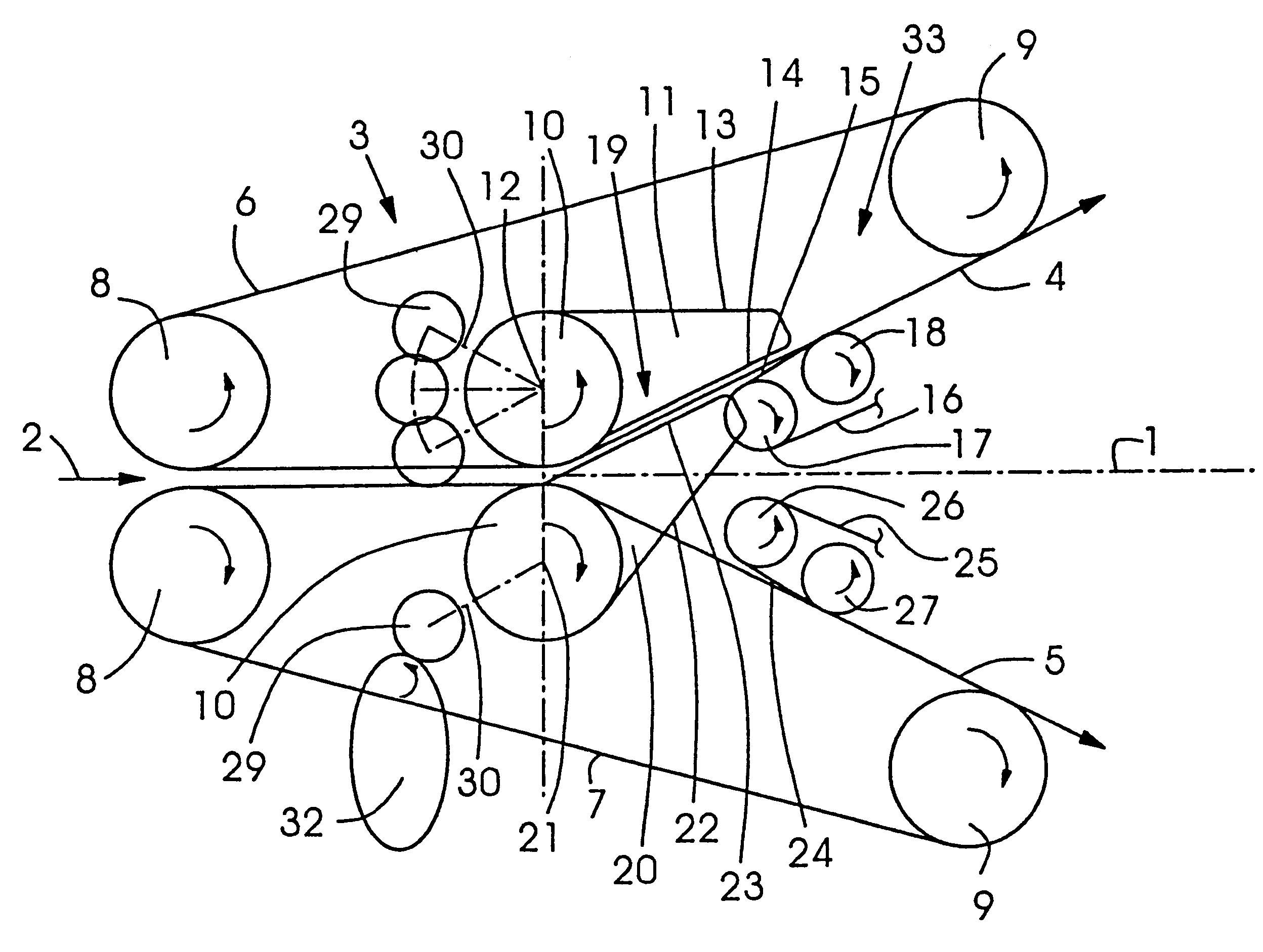
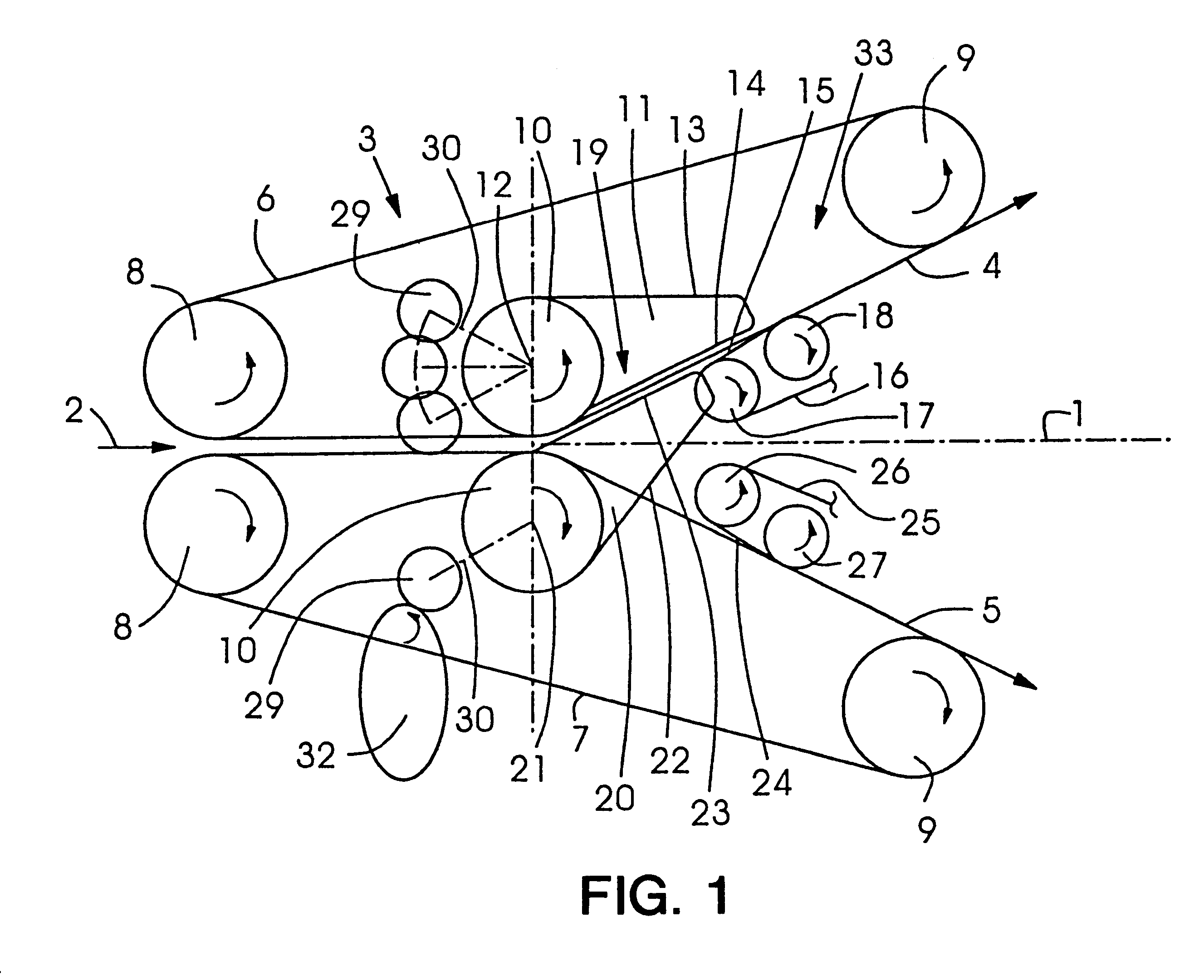
FIG. 1 shows a diverter assembly 3 having two diverter guide members 13, 22 which are moved both into an upward position to allow for diverting products into an first upper product exit path 4. On both sides about the product travel plane 1 exit tape paths do not need to be symmetrical about the entry plane 2 or travel plane 1 an upper set of supply tapes 6 and a lower set of supply tapes 7, is arranged. Said upper and lower set of supply tapes 6, 7, respectively, move about an entry tape roll 8, an exit tape roll 9, and said supply tapes 6, 7 respectively are deflected by an intermediate tape pulley shaft 10. To allow for easy access to the upper product travel plane 4, said upper set of supply tapes 6 can be swung away in a rotational movement about its first entry tape roll 8 or some other pivot point. The swinging open movement can be facilitated by assigning an air cylinder to said upper set of supply tapes 6 which facilitates the rotational movement. In the alternative, it is ...


PUM

PropertyMeasurementUnit
Transport propertiesaaaaaaaaaa

Abstract

The present invention is related to a diverting device for a continuous sequence of flat products travelling in a product travel plane. A first product exit path and a second product exit path emerge both from said product travel plane. An upper set of supply tapes and a lower set of supply tapes each comprise actuatable diverter guide members, respectively. The diverter guide members, form upper and lower diverting planes, respectively, with exit tapes upon movement of the diverter guide members about respective axes.

Description

The present invention is related to an apparatus for diverting a continuous ingoing stream of flat products such as sheets or signatures to be divided into alternate outgoing paths for further processing thereof.BACKGROUND INFORMATIONEP 0 444 507 B1 is related to a controllable diverter in a paper transport device, in particular a web-fed rotary printing machine. A diverter segment is provided having an appropriate sequence, the diverter segment itself can be pivoted back and forth in signature cycle for splitting a continuous stream of signatures into two part streams, where the signatures are supplied to the diverter and guided away therefrom by means of conveyor belts, having a diverter segment. The guide face has a ramp face for the signature which, in a limit position of the diverter segment, forms an acute angle .alpha., .beta. with the conveyor belt. A first end of the diverter segment facing the entry of the signature has a thickness which is equal to or a multiple of the th...

Claims


Application Information

Patent Timeline
IPC IPC(8): B65H29/00B65H29/60B65H29/12
CPCB65H29/12B65H29/60B65H2301/44822B65H2404/261B65H2404/631B65H2701/1932
Inventor WINGATE, MARK ANTHONY
Owner SHANGHAI ELECTRICGROUP CORP
Why Eureka
Try Eureka