

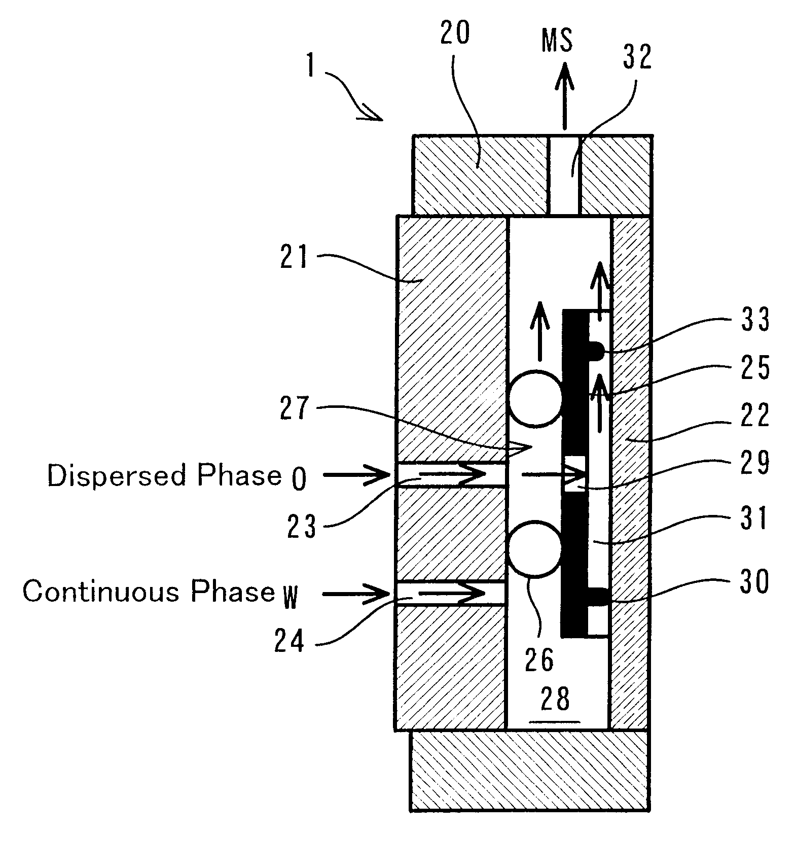
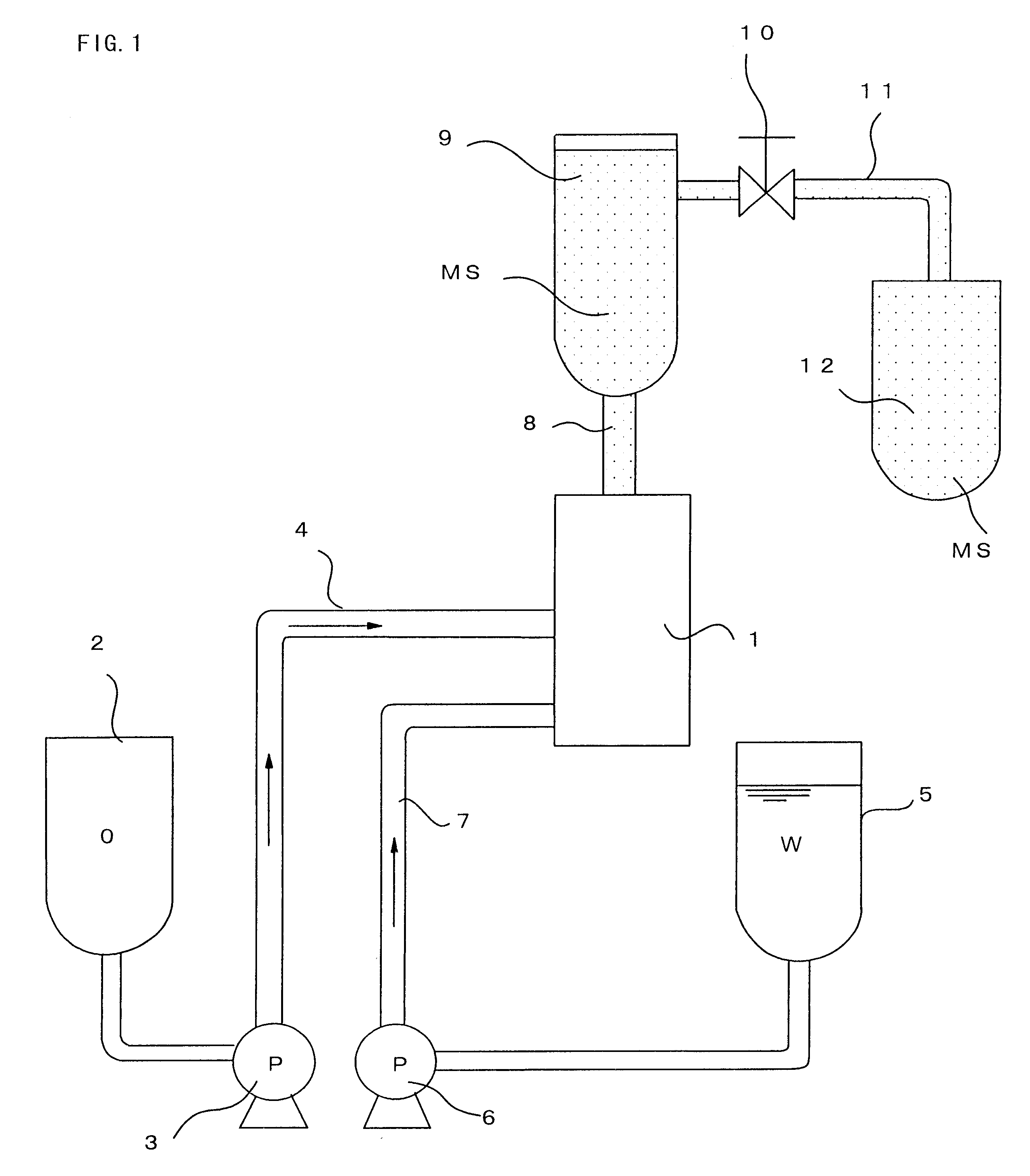
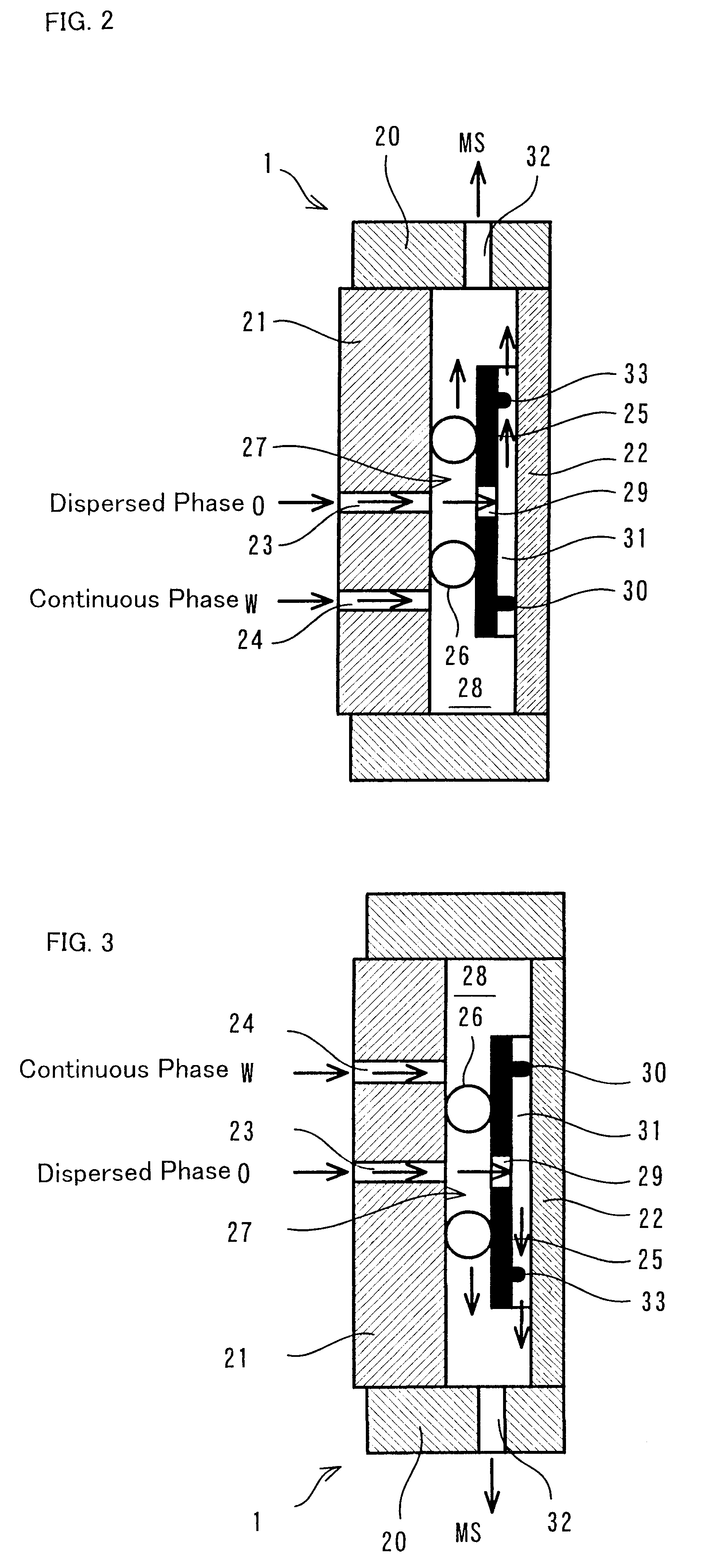
Continuous manufacturing method for microspheres and apparatus therefor
a manufacturing method and technology of microspheres, applied in the direction of drug compositions, other chemical processes, separation processes, etc., can solve the problems of inability to manufacture emulsions comprising particles smaller, the diameter of dispersed phase particles in a continuous phase is distributed over a wide range, and the inability to separate particles larger
- Summary
- Abstract
- Description
- Claims
- Application Information
AI Technical Summary
Problems solved by technology
Method used
Image

Examples
embodiment
(Embodiment)
Triolein including sorbitanmonolaurate 0.3% by weight was used as the dispersed phase, water was used as the continuous phase, the driving pressure was set at 1.08 kPa, 1.26 kPa, 1.35 kPa, or 2.44 kPa, and the manufacture of microspheres was tried. The results of this is shown in FIGS. 8-11.
As shown in FIGS. 8-10, if the driving pressure is set at a small value (1.08-1.35 kPa), the dispersed phase cannot be pumped into the continuous phase, and therefore, microspheres cannot be obtained. However, as shown in FIG. 11, if the driving pressure is raised to 2.44 kPa, the dispersed phase can be pumped into the continuous phase via the microchannels, thus forming microspheres.
In regard to the apparatus of FIG. 14, which the inventors of the present invention formerly proposed (disclosed in International Publication No. WO97 / 30783), it is disclosed that microspheres (emulsions) cannot be obtained before the driving pressure is raised to 8.38 kPa. As will be understood, the appa...
PUM
| Property | Measurement | Unit |
|---|---|---|
| particle sizes | aaaaa | aaaaa |
| driving pressure | aaaaa | aaaaa |
| driving pressure | aaaaa | aaaaa |
Abstract
Description
Claims
Application Information