Plant cultivation mat and method for laying the same

a technology for planting and mats, applied in turf growing, horticulture, agriculture, etc., can solve the problems of large-scale work, high cost, and inability to adopt equipment in existing buildings, and achieve the effect of reducing cost, short time period, and facilitating cultivation

Inactive Publication Date: 2001-01-30
KYODO KY TEC CORPORATION
View PDF8 Cites 60 Cited by
  • Summary
  • Abstract
  • Description
  • Claims
  • Application Information

AI Technical Summary

Benefits of technology

As described at the outset, the advantage of the present invention is that the laying and removing works of the plant cultivation mat can be done in an extremely easy manner and in a short period of time, and yet at the minimum cost, because one or more dismountable and light weight plant cultivation mats are laid on the mat laying surface.
In addition, by simply laying, on the mat laying surface, a plurality of plant cultivation mats, each having an inward recess formed at the lower part of the side wall of the cell, or by filling the cells on the mat laying surface, with their side walls, the lower part of which is inwardly recesed, being opposed each other, there will be defined a space for disposing water feeding pipe having a required route at the lower parts between the mutually opposed side walls of the cells, which contributes to excellent working efficiency of the plant cultivating facility.
Further, by providing a flat shaped water holding layer (or a water reservoir layer) on the mat laying surface of the plant cultivation mat, a part of excess water, such as irrigation water by watering-pot, etc., rain water, and others from above the plant cultivation mat is absorbed and stored in this water holding layer through the water passage port formed in the bottom part of each cell without its being drained, if and when the plant growing ingredients (earth brought from other place and mixed with the soil, light weight artificial soil, and so forth) are filled in the plant cultivation mat for the purpose of sowing seeds, or planting grasses and shrubs, or else.
On account of this, in case the plant growing ingredients in the cell should run short of water, the water content in the water holding layer should be conducted through the openings perforated in the bottom part of the cell, introduced into the water passage port by the capillary action, and absorbed into the plant cultivation mat. Owing to this, the water holding layer constitutes the water supply source for the plant growing ingredients, which alleviates any anxiety of water-shortage to thereby greatly contribute to the growth of seeds and plants, thus facilitating their controls.
Furthermore, by disposing the water supply pipe in the space for laying water supply pipe over the surface of the water holding layer, and by feeding water through small perforations formed around the water supply pipe, the required amount of water can be stored in the water holding layer. As the consequence, if and when the water content in the soil filled in the plant cultivation mat runs short, the water is taken into the mat through the water-passage port perforated in the bottom part of the plant cultivation mat, whereby the seeds spread over the plant growing ingredients or nurturing of the plants on the plant cultivation mat can be maintained favorably, which further facilitates control of the plant cultivation mat.
Both peripheral edge rib 8a and connecting rib 8b are required to have their thickness such that they are given flexibility to sufficiently conform to irregularity on the mat laying surface (slab), and others, and that, at the same time, they have mechanical strength of an extent such as to permit the mat frame 2 to withstand against crushing, even when a person treads on the mat frame 2 either directly or by way of walking board. In this manner, the mat frame 2 is sustained by the bottom part 3b of a plurality of cells 3 to exhibit a sense of stability, even if it is subjected to bending, hence it takes a shape that can be laid over the slab surface such as roof-top, etc. Incidentally, depending on occasion, the connecting rib 8b can be provided as a separate body.

Problems solved by technology

With the abovementioned method of spreading soil, however, there arises necessity for providing outfits such as water-prevention layer, etc., which give rise to various problems such that the equipment can hardly be adopted in those existing buildings, while cost to be borne would increase when it is adopted in new buildings.
Furthermore, a large-scaled working becomes necessary for utilization of the abovementioned plant cultivating facility, which requires enormous amount of time and labor.
Again, enormous amount of time and labor are needed for this removing work.

Method used


Image

  • Plant cultivation mat and method for laying the same
  • Plant cultivation mat and method for laying the same
  • Plant cultivation mat and method for laying the same

Examples


first embodiment

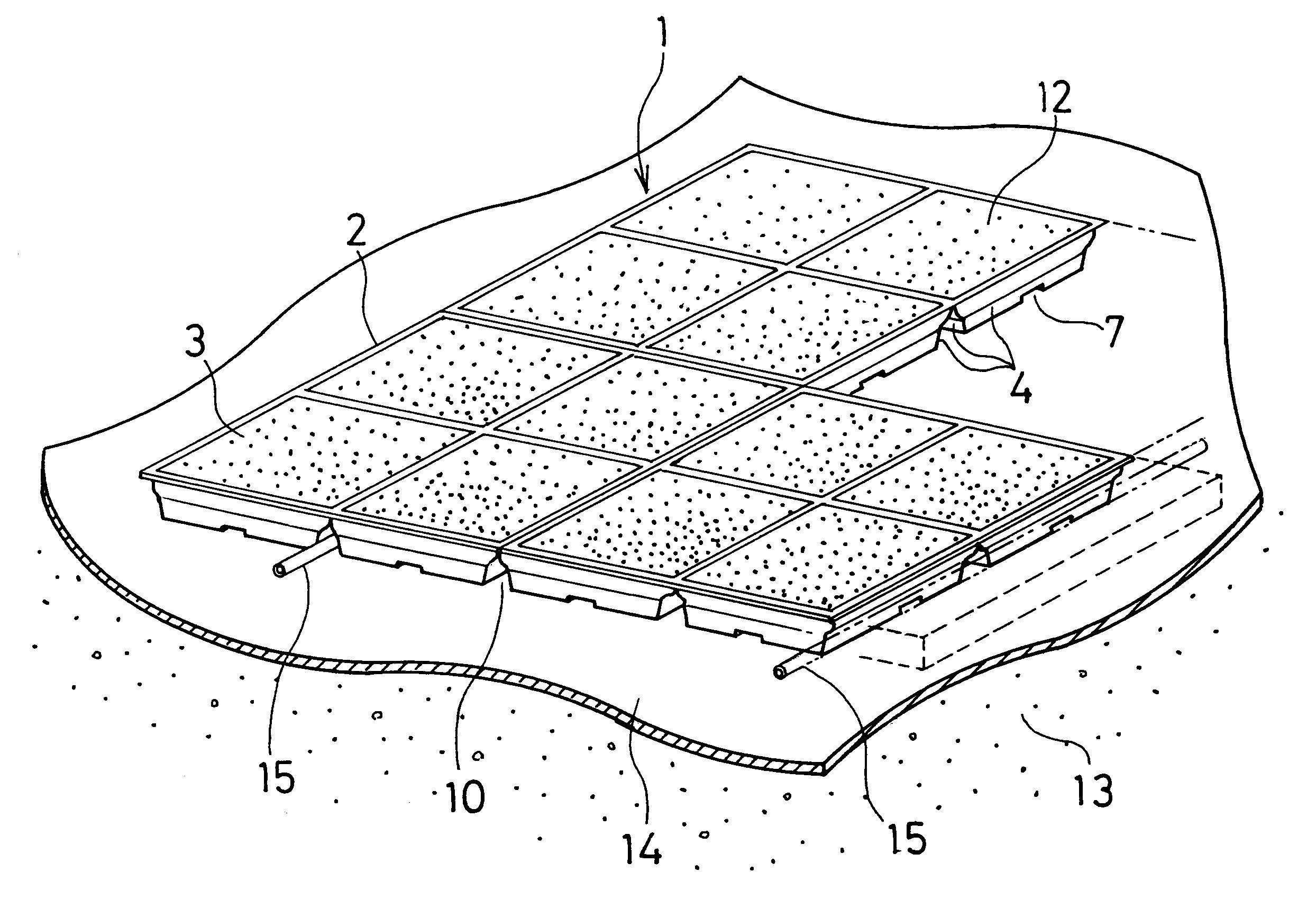
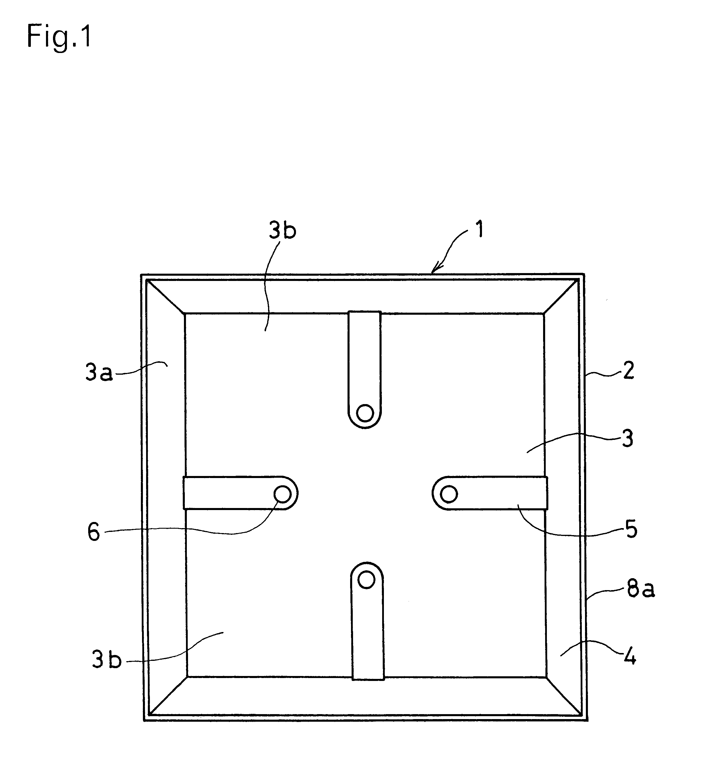
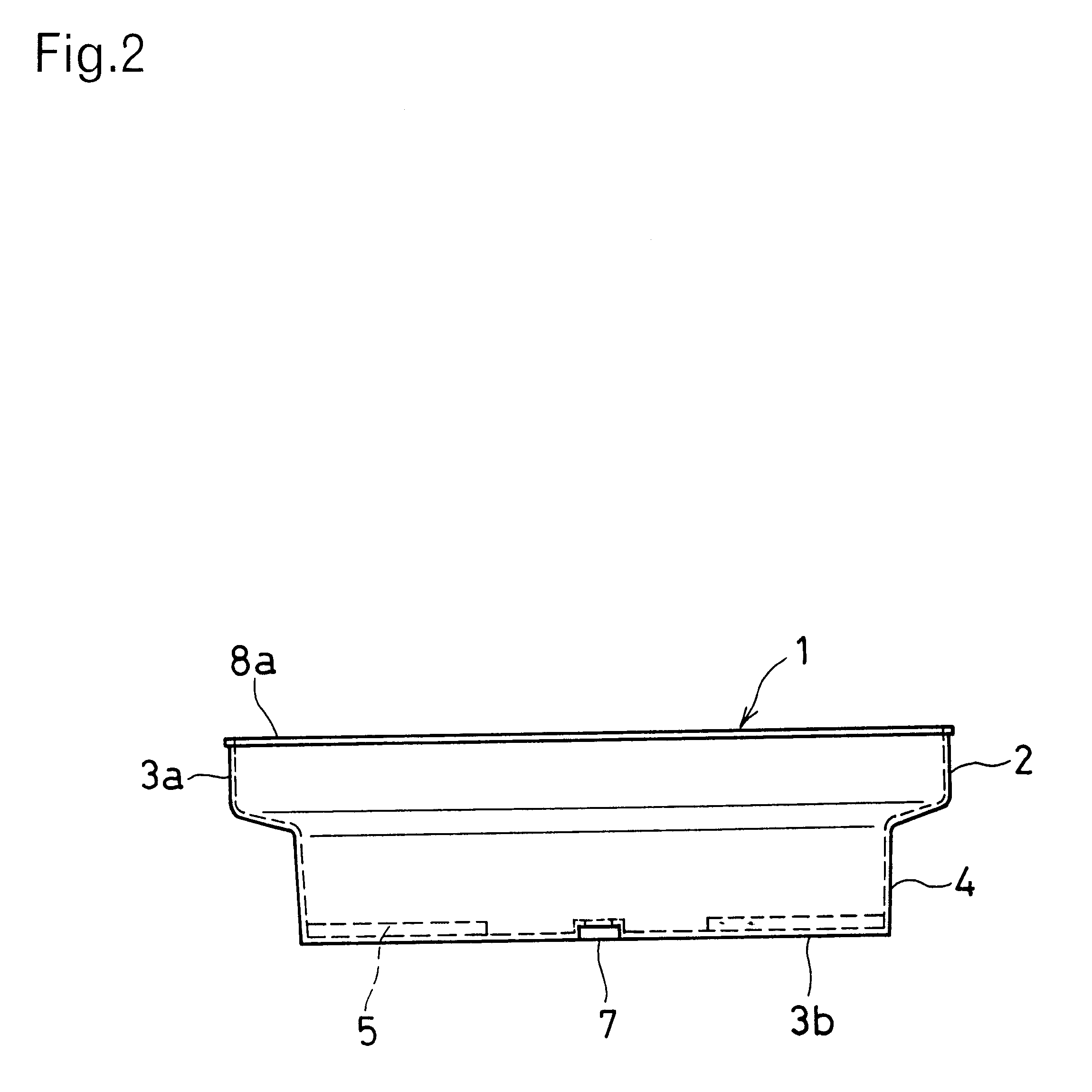
As shown in FIGS. 1 to 3, the plant cultivation mat 1 according to the present invention is made up of a square mat frame 2 consisting of a single cell 3 which is so depressed as to permit its top part to open, an inwardly recessed part 4 being formed at the lower part of the four side walls 3a of the cell 3.

Raised parts 5 are formed from the lower part of the side walls 3a of the cell 3 toward the center of its bottom part 3b, a water passage port 6 being perforated at an appropriate location in the upper end surface of each of the raised parts 5, situated in the vicinity of the center of the bottom part 3b. The inside of the raised part 5 is of such a construction that it constitutes a space in an inverted "U" shape, and has an opening 7 in a depressed groove, excess water being discharged outside through this groove-shaped opening 7. The shape, size, number, and so on of the water passage port 6 and the opening 7 are determined arbitrarily in accordance with the construction of t...

second embodiment

In the next place, explanations will be given as to the plant cultivation mat 1 according to the present invention. As shown in FIG. 7, the plant cultivation mat 1 is formed of a square mat frame 2, each of the four walls 2a of the surrounding side faces forming an inwardly recessed part 4 at its lower part. Within the mat frame 2, there is disposed a partition member 9 in a cross-shape, at a height not exceeding the upper end of the mat frame 2, i.e., at a height in flush with, or slightly lower than, the peripheral rib 8a of the mat frame 2, thereby defining four cells 3 in the mat frame 2.

Besides the example as illustrated in the drawing, the partition member 9 has its shape of intersection, grating, and others. This partition member 9 can also be molded as an integral part of the mat frame 2, or be disposed inside the mat frame 2 as a separate member, or may take any other arbitrary configuration. Such construction of the partition member 9 can be applied to the plant cultivatio...

second modified example

this second embodiment is of such a construction that, as shown in FIG. 9, the mutually adjacent two side walls 2a out of the four side walls 2a are inwardly recessed at their lower part to thereby form the inwardly recessed part 4, and that the other two adjacent side walls 2a form the mildly and inwardly tapered faces extending from their top to the bottom.


PUM


Abstract

This invention is to provide a plant cultivation mat which can be applied to those existing buildings, and which does not require large amount of time, labor and cost for its laying and removing works, and a method for laying such plant cultivation mat, as well. According to the invention, there is provided a plant cultivation mat, comprising one or a plurality of cells with water-passage ports being perforated in the vicinity of the bottom part thereof, said one or a plurality of cells constituting a mat frame disposed in a depressed form to permit the top part thereof to open, and an inwardly recessed part being formed at the lower required part of the side wall of said cell. When this plant cultivation mat is to be laid, arrangement is made as to forming a space having a required route at the inwardly recessed part of the cell so as to form a space having a required routein the inwardly recessed part of the cell. Before the plant cultivation mat is to be laid on the mat laying surface, a water holding layer is provided beforehand. It is further preferable that, at the time of filling the laying surface with this plant cultivation mat, the space having a required route is formed, and simultaneously water supply pipe is disposed in an arbitrary route in said space.

Description

a) Field of the InventionThis invention relates to a plant cultivation mat (or grass growing mat) to be laid on the roof top, veranda, terrace, etc. of buildings (in particular, an artificial ground) for growing various plants such as, especially, ground-covering plants like lawn, etc., grasses, flowers, vegetables, and so forth, and to a method for laying such plant cultivation mat.b) Description of Prior ArtsIt has been the conventional practice that, when cultivating or growing plants at a location having flat laying surface such as the roof top, veranda, terrace, etc. of buildings, a water-prevention layer and a root-protecting layer is formed, or a sheet is further laid thereover, and then soil is spread over the sheet to cultivate ground-covering plants such as lawn, grasses and shrubs, vegitables, and so forth (vide: for example, laid-open gazette of Japanese Patent Application No. 4-99411).With the abovementioned method of spreading soil, however, there arises necessity for ...

Claims


Application Information

Patent Timeline
Patent Type & Authority Patents(United States)
IPC IPC(8): A01G9/02A01G1/00
CPCA01G9/02A01G1/007A01G9/033A63B55/57
Inventor YOSHIDA, MINORUKUMURA, KAZUOYOSHIOKA, TAKAHARUUCHIDA, SHINJI
Owner KYODO KY TEC CORPORATION
Why Eureka
Try Eureka