Cooling chamber temperature control device

a temperature control device and cooling chamber technology, applied in the direction of domestic cooling devices, heating types, instruments, etc., can solve the problems of inability to accurately measure significant temperatures, inability to integrate the smallest temperature sensors which operate virtually without inertia in the outermost surface layer of the specimen, and considerable drawbacks and shortcomings

Inactive Publication Date: 2001-01-30
LEICA MICROSYSTEMS (SCHWEIZ) AG
View PDF4 Cites 33 Cited by
  • Summary
  • Abstract
  • Description
  • Claims
  • Application Information

AI Technical Summary

Problems solved by technology

In everyday practice, however, this principle exhibits considerable drawbacks and shortcomings which stem from the technical options available for precise temperature measurement in extremely small areas.
Currently, it is technically impossible to measure the significant temperatures correctly.
Even the smallest temperature sensors which operate virtually without inertia (e.g. microthermocouples) cannot be integrated in the outermost surface layers of the specimen.
It is not possible to arrange sensors at the actual cutting edge either in the diamond cutters which are preferably used nowadays in ultramicrotomy or in the less expensive metal or glass blades.
This makes it almost impossible to reproduce the temperatures, particularly if cooling chambers of different designs or from different manufacturers are used.
The situation becomes pa

Method used


Image

  • Cooling chamber temperature control device
  • Cooling chamber temperature control device

Examples


Embodiment Construction

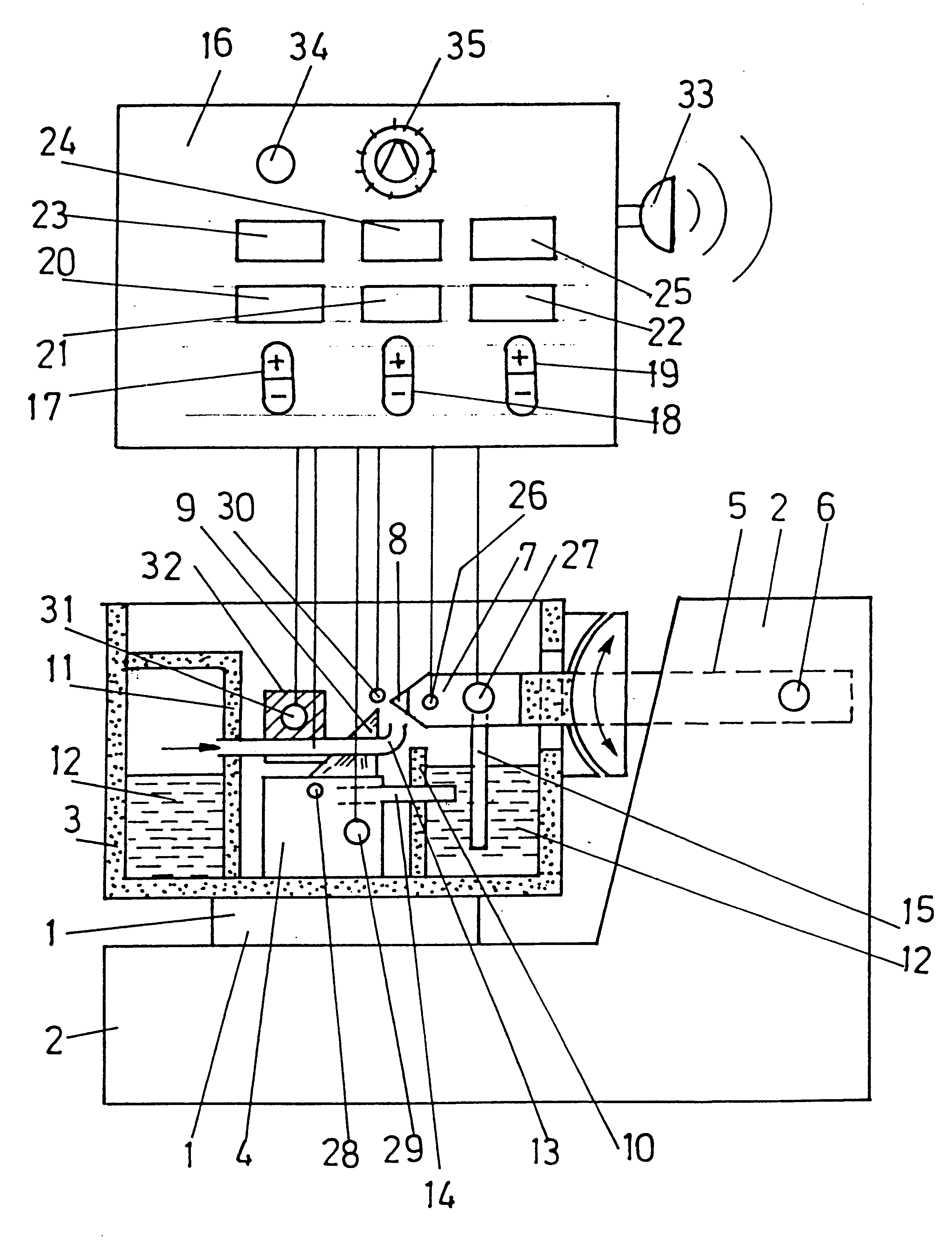
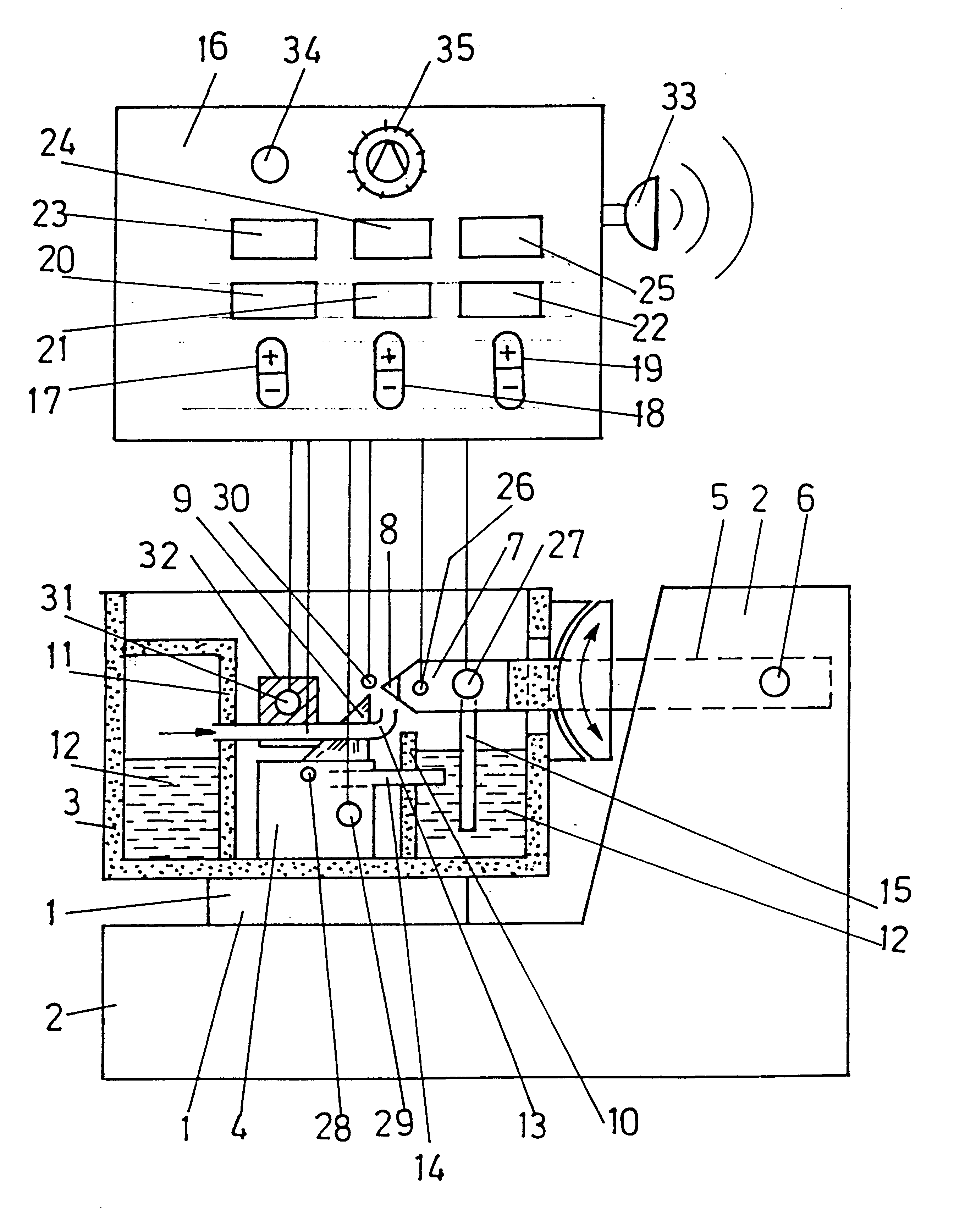
The microtome / ultramicrotome illustrated in FIG. 1 is similar in several respects to a conventional design (cf. in this respect also H. Sitte, 1983, 1.c., and H. Sitte and K. Neumann, Ultramikrotome und apparative Hilfsmittel der Ultramikrotomie [Ultramicrotomes and auxiliary apparatus for ultramicrotomy], in: G. Schimmel and W. Vogell, Methodensammlung der Elektronenmikroskopie [Collection of methods used in electron microscopy], Wissenschaftliche Verlags-GmbH, Stuttgart 1983).

As shown in FIG. 1, a cooling chamber 3 is attached to a cutter support 1 of a microtome / ultramicrotome 2. A cutter holder 4 is mounted at the bottom of the cooling chamber 3. A specimen-carrier bar 5 is introduced through the rear wall of the cooling chamber 3 and executes an oscillating up-and-down movement about a bearing 6 during the sectioning. A specimen holder 7 with a specimen 8 is attached to the free end of the bar 5 and, in the course of the cutting movement (double arrow) is guided past the cuttin...


PUM


Abstract

A device for controlling the temperatures in a cooling chamber for a microtome, in particular an ultramicrotome, comprises at least two different temperature control circuits for controlling the temperatures of the specimen and of the cutter. The control circuit for the temperature of the specimen (8) and the control circuit for the temperature of the cutter (9), as well as, if appropriate, the control circuit for the temperature of the chamber gas, have a common setting element (17), such that the control circuit can be programmed to an identical temperature as the set value.

Description

1. Field of the InventionThe invention relates to a device for controlling the temperatures in a cooling chamber for microtomes, in particular ultramicrotomes, having at least two different temperature control circuits for controlling the temperatures of the specimen and of the cutter.2. Related Prior ArtThe cutting of soft, elastic or hard samples, or, in very general terms, of materials whose consistency does not allow them to be cut at room temperature (e.g. aqueous suspensions, paints) requires cooling to temperatures which in some cases are well below room temperature. In this case, special cooling chambers are used for the microscopic, in particular electron-microscopic examination, and these cooling chambers, combined with suitable microtomes or ultramicrotomes, make it possible to remove sufficiently thin sections (cf. in this respect, inter alia, H. Sitte, Ultramikrotomie, in: mta-journal extra No. 10, Umschau-Yerlag, Breidenstein GmbH, Frankfurt-Main, 1983). The temperatur...

Claims


Application Information

Patent Timeline
IPC IPC(8): F25D29/00G01N1/04G01N1/06G05D23/19G01N1/42
CPCF25D29/001G01N1/06G05D23/193G01N1/42G05D23/1931
Inventor SITTE, HELLMUTHNEUMANN, KLAUSHAESSIG, HELMUT
Owner LEICA MICROSYSTEMS (SCHWEIZ) AG
Why Eureka
Try Eureka