

Underground acoustic wave transmitter, receiver, transmitting/receiving method, and underground exploration using this
a technology of transmitting/receiving method and sub-surface acoustic wave, which is applied in the direction of measurement device, seismicity, instruments, etc., can solve the problems of disabling the satisfactory investment to be carried out, disabling the measurement between the bore holes, and hydraulic system not being able to exhibit stable output in a wide frequency rang
- Summary
- Abstract
- Description
- Claims
- Application Information
AI Technical Summary
Problems solved by technology
Method used
Image

Examples
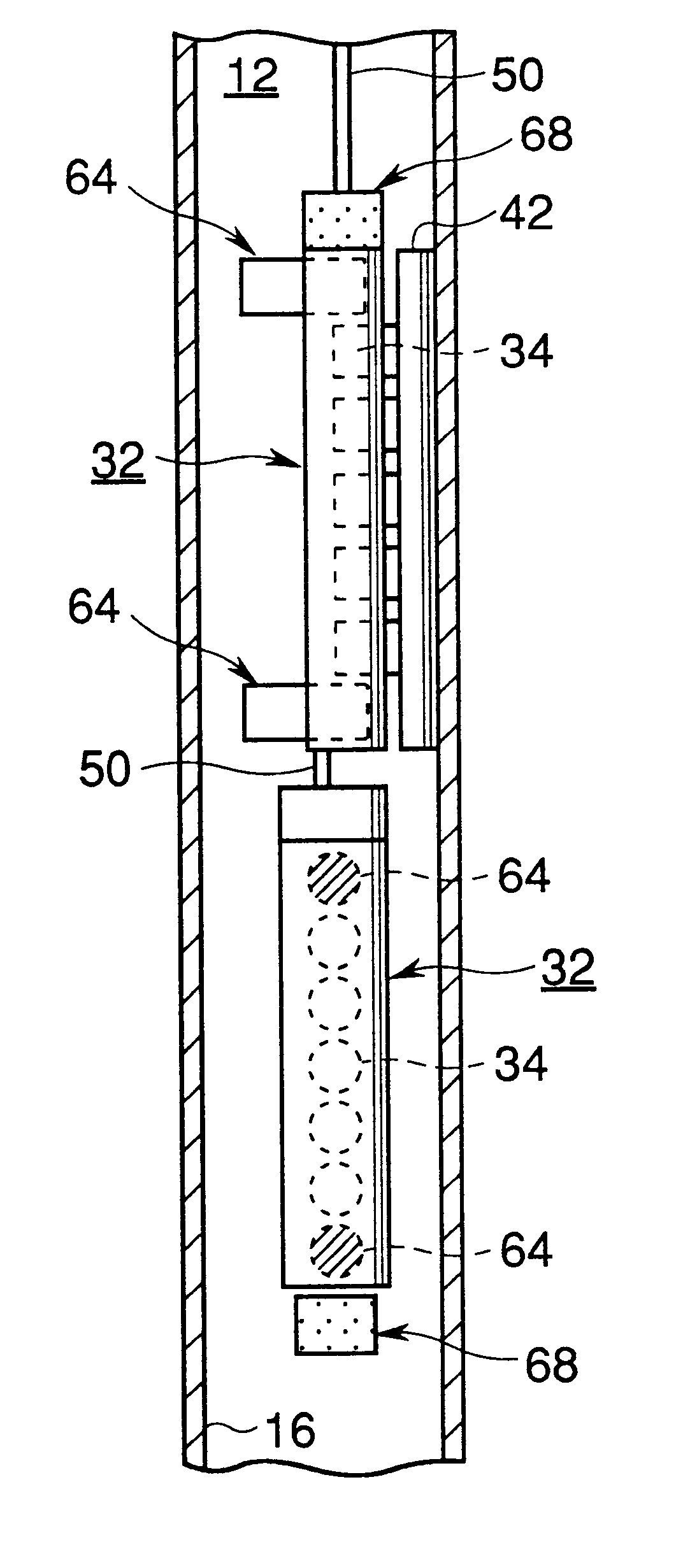
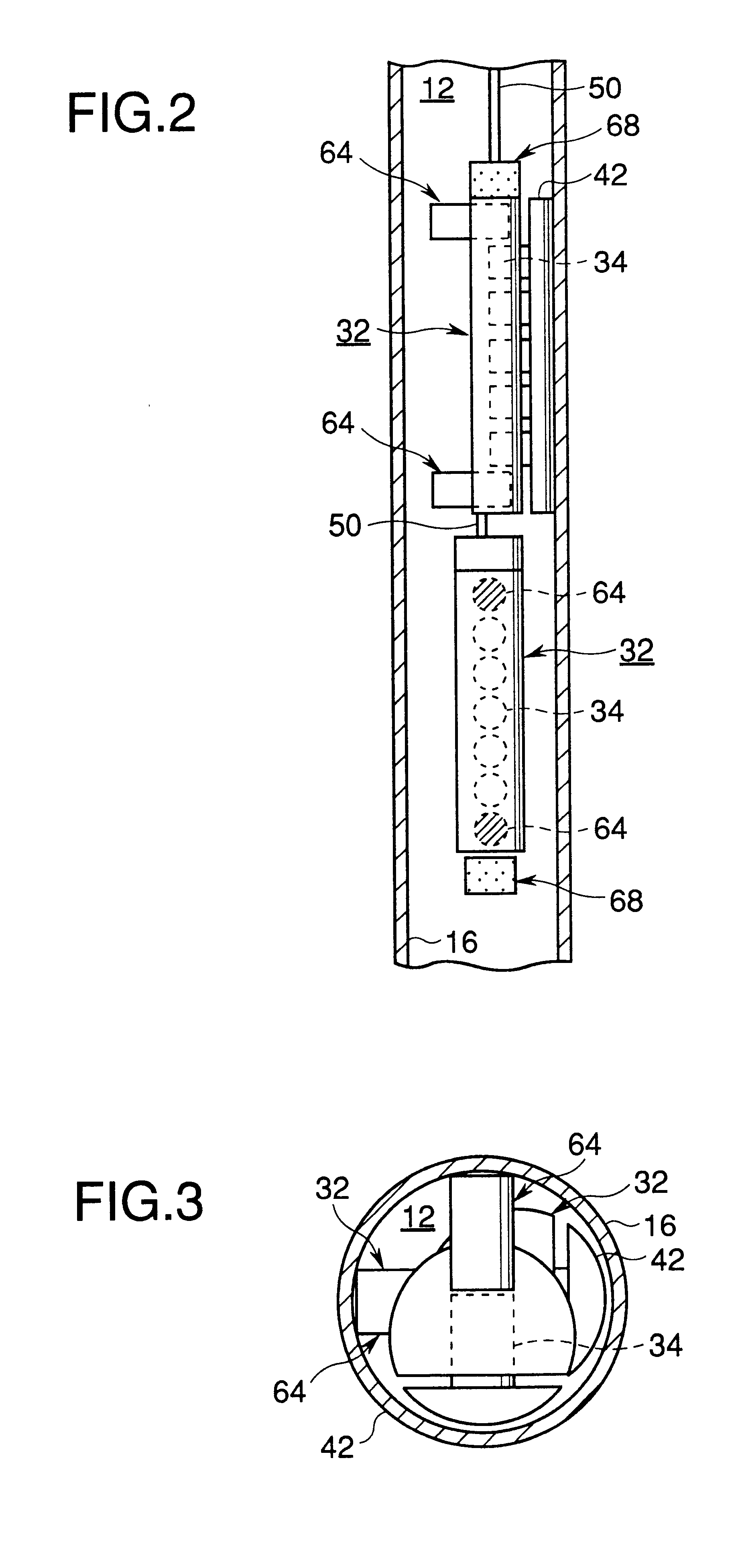
first embodiment
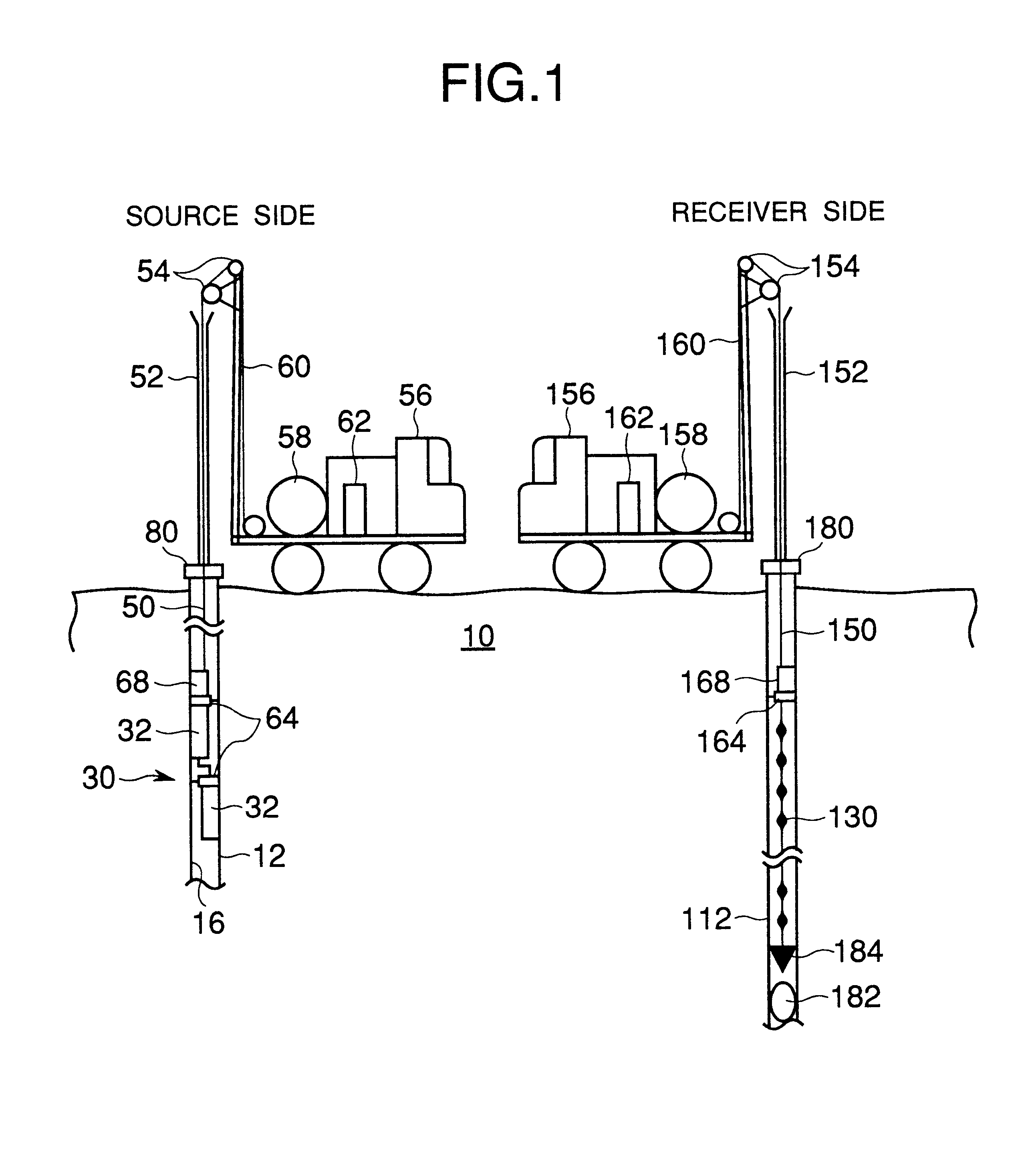
FIG. 1 shows a state in which an underground exploration method is executed using a vibration transmitting device and a vibration receiving device according to the present invention.
A vibration transmitting device 30 according to the present invention is installed in a well 12 cased by a steel pipe on a source side, by a source side sheathed electric cable 50 of high voltage. The cable 50 is lubricated by a grease in a lubricating pipe 52 arranged on the well 12 in order to facilitate its installation, and the tension of the cable 50 is balanced by a tension balance pulley 54 disposed at the highest location of the rig. This tension balance pulley 54 relieves the over-tension of a cable winding electric winch 58 to protect the cable and the equipment.
The vibration transmitting device 30 is movable up and down in the well 12 by, for example, the winch 58 mounted on a truck 56 and the well tower 60. The vibration transmitting device 30 is fixed at a depth suitable for the measurement ...
second embodiment
Moreover, like the vibration transmitting device shown in FIG. 12, between the vibrator 32 and the cable 50 can be disposed a turning mechanism 200 including, for example, a direction control gyroscope and motor 202, a hydraulic clamping mechanism 204, and a connecting rod 206, thereby making the vibrator 32 rotatable in the casing 16, which enables the longitudinal or the transverse wave to be propagated in an arbitrary direction.
The main body of the vibrator according to this embodiment is controlled so as to be directed in such a direction to emit the vibration, by the direction control gyroscope and motor 202, which enables a directional acoustic wave to be emitted.
In concrete terms,
1. To monitor the gyroscope and then confirm the current direction of the vibrator.
2. To rotate the main body in such a direction (direction of receiver) as to emit the vibration by the direction control motor (electric drive).
3. To extend the hydraulic clamp (204) after controlling the direction, an...
fourth embodiment
There is shown in FIG. 14 (side view) and FIG. 15 (lateral sectional view) a vibration transmitting device using a spring type clamp 400 according to the present invention.
Further, an electromagnet may be attached to the anvil and the anvil may be magnetized electrically in measurement so as to raise the pressure-fitting effect to the iron casing.
Besides, the vibration direction may not be restricted to the vertical to the wall of the bore hole. Like a fifth embodiment shown in FIG. 16, the hole wall may be moved up and down by vibrating a mass body 502 (the lower source vibrator 32 in the first embodiment may be available) hung from a body 500 (the upper source vibrator 32 in the first embodiment may be available) fixed to the wall of the bore hole by a pair of left and right hydraulic pistons 66A, 66B.
The comparisons of the source output in terms of the strike force for the source vibrator according to the first embodiment and a conventional source vibrator in a steel cased well, ...
PUM
 Abstract
Description
Claims
Application Information