Articulating spinal implant

a spinal implant and articulating technology, applied in the field of spinal implants, can solve the problems of one or more intervertebral disc shrinkage, collapse, deterioration or displacement, herniation or other damage, chronic and often disabling pain, and irreversible paralysis of the upper and/or lower limbs

Inactive Publication Date: 2001-01-30
WARSAW ORTHOPEDIC INC
View PDF43 Cites 788 Cited by
  • Summary
  • Abstract
  • Description
  • Claims
  • Application Information

AI Technical Summary

Problems solved by technology

Injury, disease or other degenerative disorders may cause one or more intervertebral discs to shrink, collapse, deteriorate or become displaced, herniated or otherwise damaged.
This can lead to compression of adjacent nerve root(s) or the spinal cord causing chronic and often disabling pain, and in advanced circumstances, irreversible paralysis of upper and / or lower limbs.
This procedure disadvantageously requires the harvest of donor bone for the graft from other parts of the patient's body, typically requiring a separate surgical procedure and resultant increases in complications and expense.
Fusion of adjacent vertebrae necessarily eliminates a portion of the spine's normal range of motion, thereby reducing the subject's spinal flexibility.
Additionally, fusion of the vertebrae increases the stresses imposed on adjacent mobile portions of the spinal column, often hastening the subsequent breakdown of normal joint surfaces above and below the fused vertebrae.
Previously-known devices of this type generally have been found to suffer from inadequate attachment between the prosthesis and the vertebrae.
Because such motion would disrupt bone ingrowth, jointed prostheses have generally been considered incompatible with attachment by bone ingrowth.
These mechanisms of attachment, however, may lack the degree and strength of fixation desired.
This has been found undesirable, as the extending flanges may interfere with or injure adjacent tissue.
For example, it has been reported that flanges extending into immediately adjacent delicate esophageal area may interfere with swallowing and speech, or cause perforation and potentially fatal infection.
An additional drawback to the use of screw and pin connections is the potential for such connectors to dislodge and cause injury.

Method used


Image

  • Articulating spinal implant
  • Articulating spinal implant
  • Articulating spinal implant

Examples


Embodiment Construction

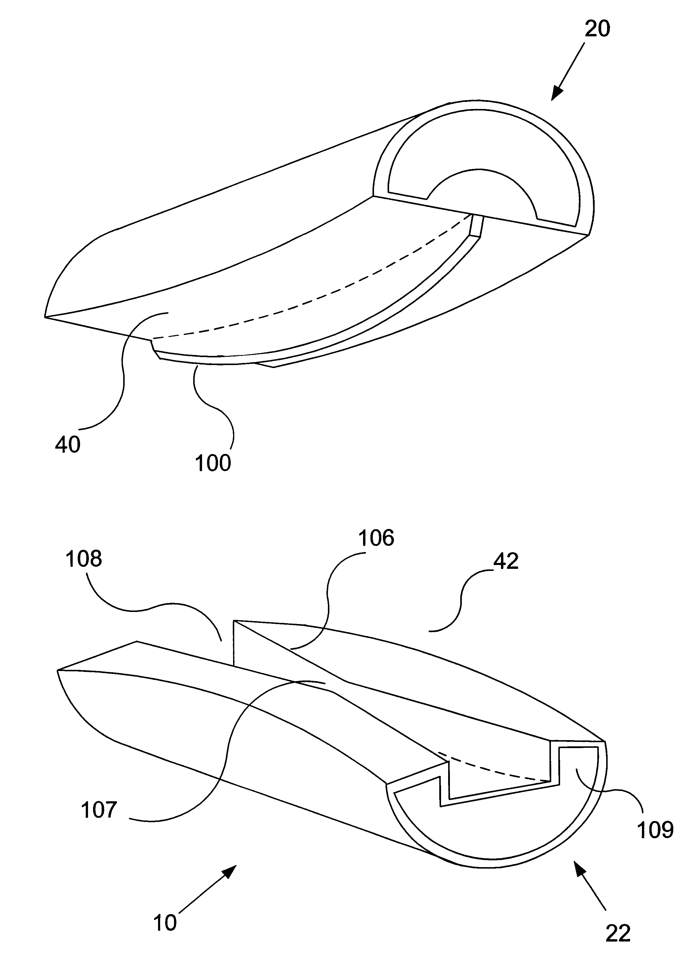
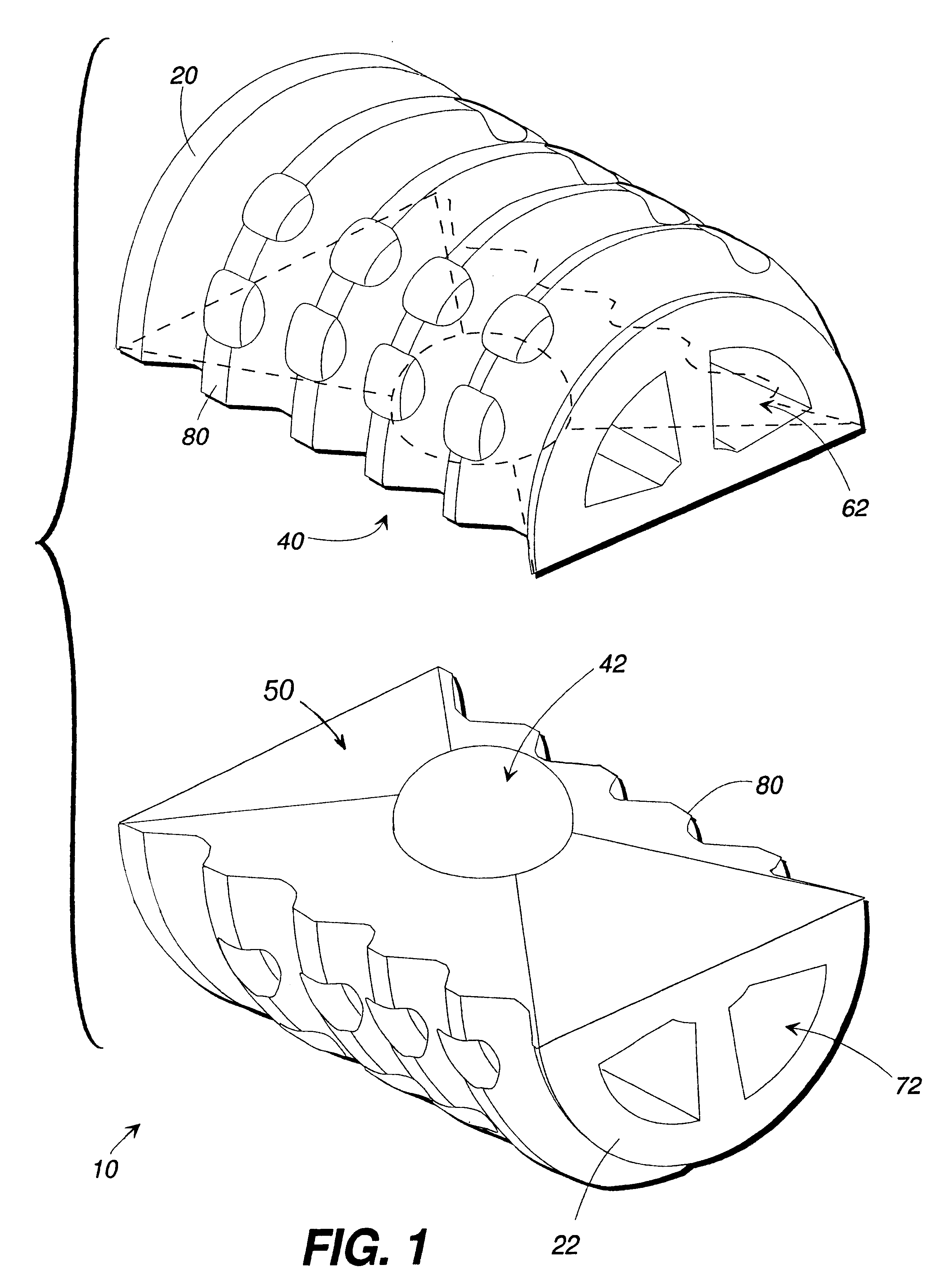
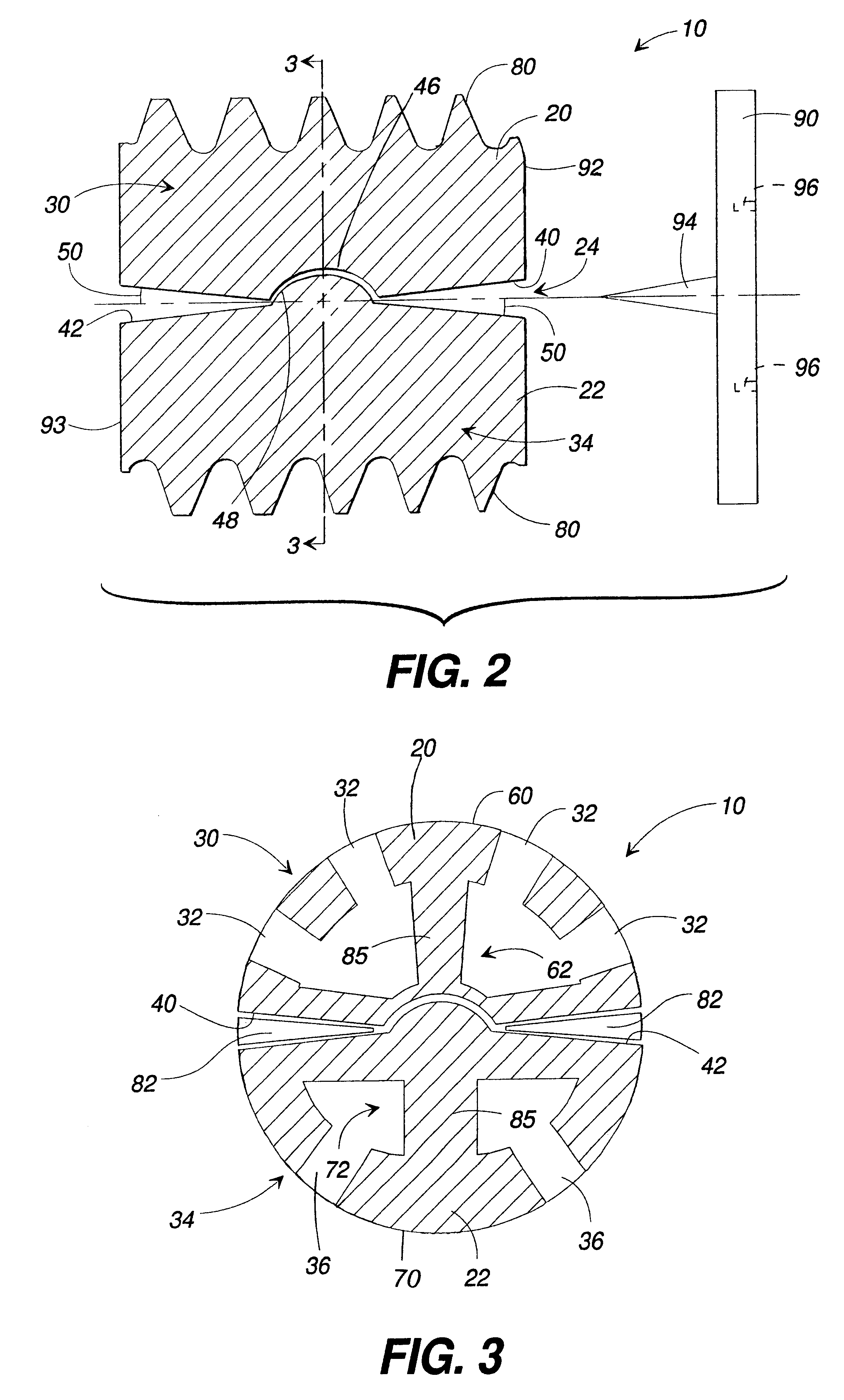
Referring now in detail to the figures wherein like reference numbers represent like parts throughout, preferred forms of the present invention will now be described. As seen in FIGS. 1-3, one embodiment of the present invention comprises a spinal implant 10, generally comprising a first element 20 and a second element 22. The first element 20 is coupled to the second element 22 by an internal articulation means 24 for allowing relative pivotal movement between the first and second elements.

FIGS. 4A and 4B show the spinal implant 10 of the present invention installed in situ, between a first vertebra 12 and a second vertebra 14. The implant 10 is shown implanted into an anterior aspect of the vertebral body, between the fifth cervical and sixth cervical vertebra. The device and method of the present invention, however, are applicable to anterior and posterior approaches to the vertebrae.

As seen best in FIGS. 2-3, the first element 20 of the implant 10 comprises first connection mean...


PUM

PropertyMeasurementUnit
widthaaaaaaaaaa
vertical radiusaaaaaaaaaa
flexibilityaaaaaaaaaa

Abstract

A spinal implant for intervertebral disc replacement. The implant is formed from two hemicylindrical elements, each engaging one of an adjacent pair of vertebrae. An articulating ball-and-socket joint between the two elements resists compression and lateral movement between the vertebra, but allows pivotal movement, thereby preserving mobility. Fusion chambers are provided for allowing bone ingrowth to fuse the elements to the vertebrae. Biocompatible, bioreabsorbable struts, shims, fillers and/or end caps are provided for temporary stabilization of the first and second hemicylindrical elements. Bone chips removed from the vertebrae during implantation or bone growth stimulators can be inserted into the fusion chamber or otherwise applied to the implant to enhance bone ingrowth.

Description

1. Field of the InventionThe invention relates generally to a spinal implant for use in intervertebral disc replacement, and more specifically relates to an articulating implant that fuses to adjacent vertebrae by bone ingrowth, thus restoring proper intervertebral spacing, and eliminating nerve root and / or spinal cord compression, while preserving spinal flexibility.2. Description of Related ArtThe spinal column is formed from a number of vertebrae, which in their normal state are separated from one another by cartilaginous intervertebral discs. These discs form a cushion between adjacent vertebrae, resisting compression along the support axis of the spinal column, but permitting limited movement between the vertebrae to provide the characteristic flexibility of the healthy spine. Injury, disease or other degenerative disorders may cause one or more intervertebral discs to shrink, collapse, deteriorate or become displaced, herniated or otherwise damaged. This can lead to compressio...

Claims


Application Information

Patent Timeline
Patent Type & Authority Patents(United States)
IPC IPC(8): A61B17/16A61F2/44A61F2/02A61F2/28A61F2/30A61F2/00A61F2/46
CPCA61B17/1671A61F2/4425A61F2/446A61B17/1604A61F2/30724A61F2/30744A61F2/30767A61F2/442A61F2/4611A61F2002/2817A61F2002/2821A61F2002/2835A61F2002/30062A61F2002/30232A61F2002/30329A61F2002/30385A61F2002/30387A61F2002/3039A61F2002/30393A61F2002/30397A61F2002/30515A61F2002/30649A61F2002/30662A61F2002/30663A61F2002/30672A61F2002/30785A61F2002/30787A61F2002/3081A61F2002/30827A61F2002/3085A61F2002/30879A61F2002/30934A61F2002/30975A61F2002/443A61F2002/4475A61F2210/0004A61F2220/0025A61F2230/0069A61F2310/00017A61F2310/00023A61F2310/00029A61F2310/00059A61F2310/00239A61F2310/00293A61F2310/00401A61F2310/00407A61F2310/00413A61F2310/00449A61F2310/00634A61F2002/30593
Inventor CAUTHEN, JOSEPH C.
Owner WARSAW ORTHOPEDIC INC
Why Eureka
Try Eureka