Apparatus and method for controlling plasma uniformity across a substrate

Inactive Publication Date: 2001-01-30
NOVELLUS SYSTEMS
View PDF16 Cites 172 Cited by
  • Summary
  • Abstract
  • Description
  • Claims
  • Application Information

AI Technical Summary

Problems solved by technology

In conventional magnetron sputtering, the ionization levels are not high enough throughout the chamber to yield substantially more ionized sputtered metal atoms than neutral metal atoms.
Conventional magnetron sputtering has proven to be inadequate in the aforementioned appl

Method used


Image

  • Apparatus and method for controlling plasma uniformity across a substrate
  • Apparatus and method for controlling plasma uniformity across a substrate
  • Apparatus and method for controlling plasma uniformity across a substrate

Examples


Embodiment Construction

)

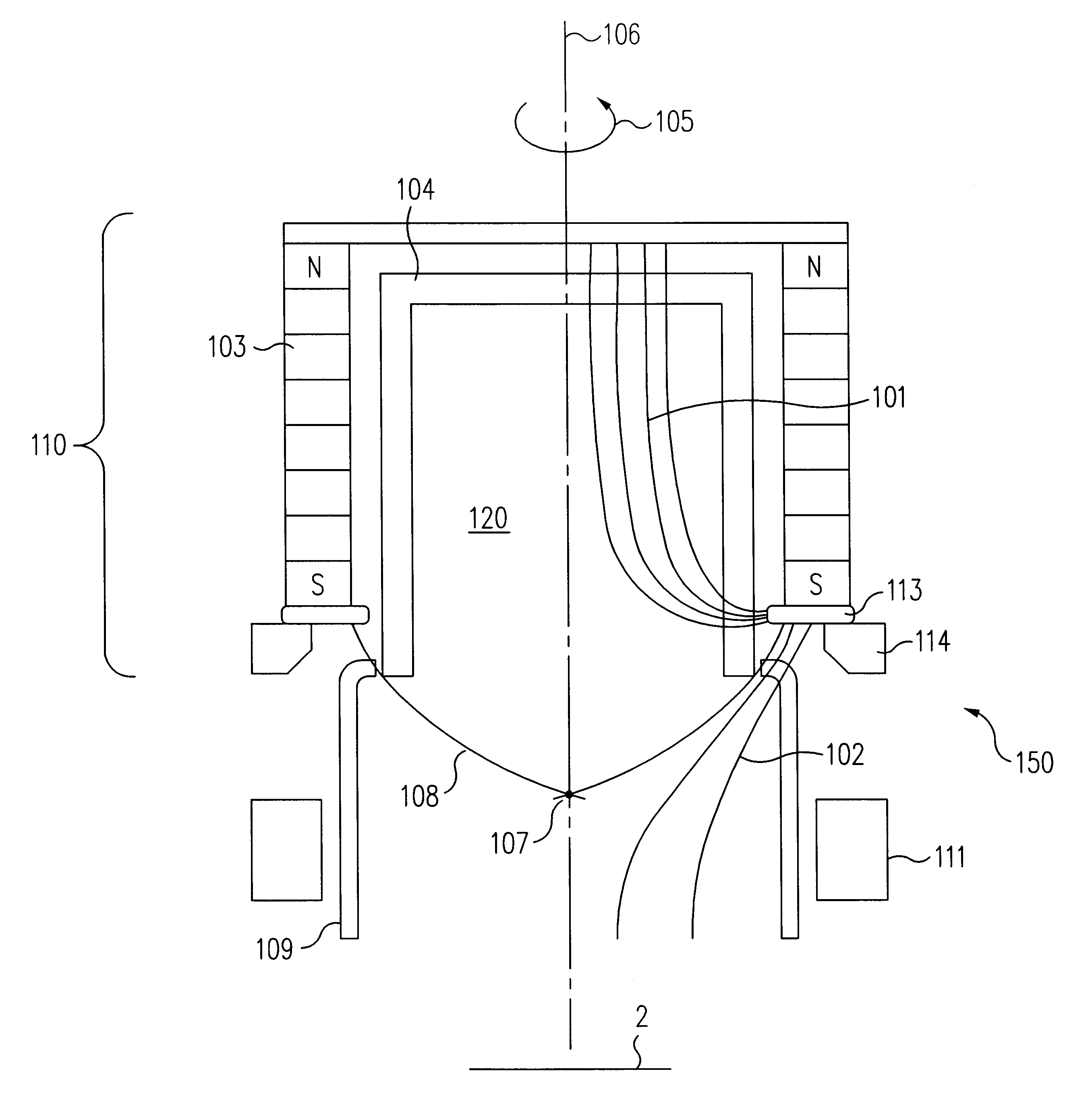
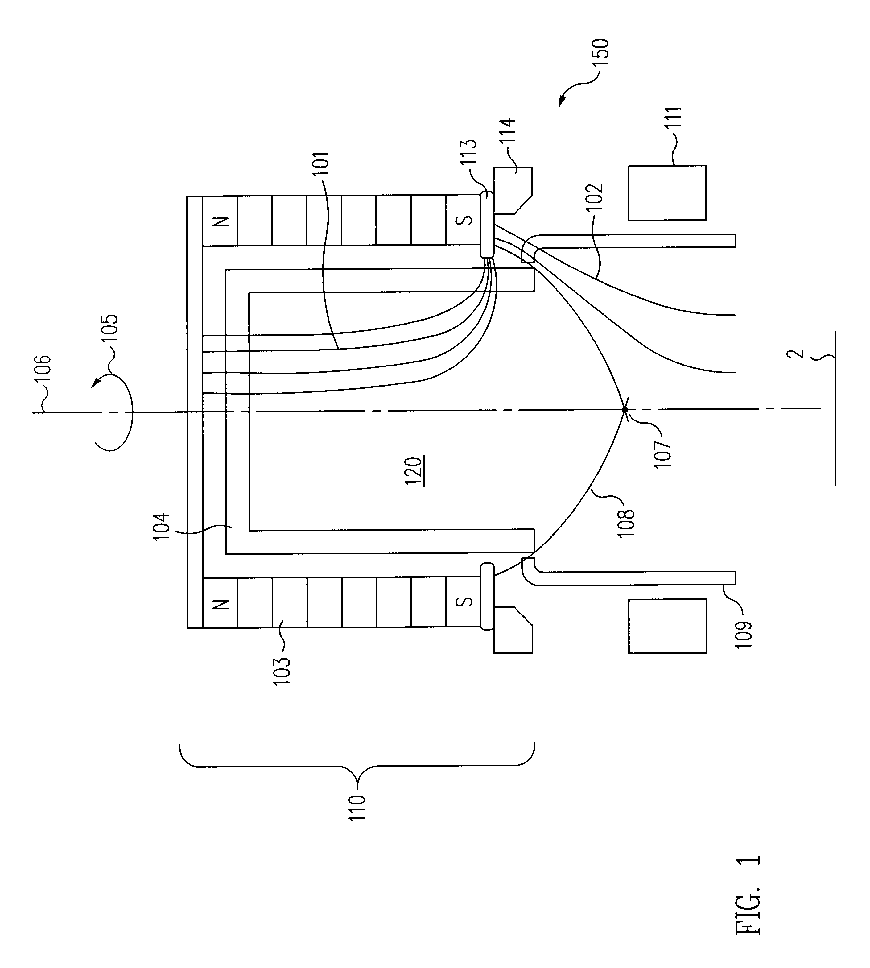
The present invention provides for a novel hollow cathode magnetron source ("HCM"). The film step coverage and uniformity are enhanced by using a novel magnetic configuration to increase ionization levels and to directionally control the flow of plasma out of the cathode. In one embodiment of the invention, the HCM is shielded to reduce magnetic leakage.

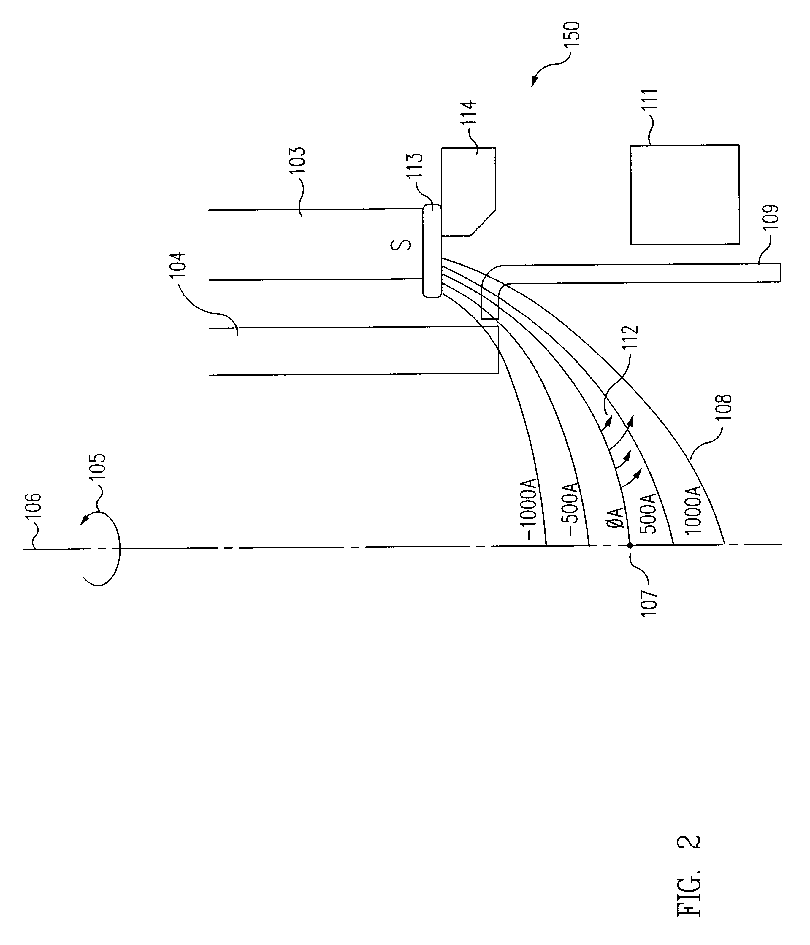
U.S. Pat. No. 5,482,611 to Helmer et. al. ("Helmer"), incorporated herein by reference in its entirety, also discloses an HCM. Helmer teaches that by providing a magnetic field having a magnetic null region at the opening of the hollow cathode, ions and electrons can be trapped and retained inside the hollow cathode except for those which have entered into the upper edge of the null region with sufficient axial velocity and very little radial velocity. Ions and electrons that have primarily axial velocity are able to leave the hollow cathode along the axis at the upper edge of the null region. Most other plasma particles, however, a...


PUM

PropertyMeasurementUnit
Densityaaaaaaaaaa
Magnetismaaaaaaaaaa
Plasma poweraaaaaaaaaa

Abstract

A novel hollow cathode magnetron source is disclosed. The source comprises a hollow cathode with a non-planar target. By using a magnet between the cathode and a substrate, plasma can be controlled to achieve high ionization levels, good step coverage, and good process uniformity.

Description

1. Field of the InventionThe present invention generally relates to sputtering apparatus and methods used in semiconductor device fabrication.2. Description of the Related ArtIn a physical vapor deposition ("PVD") process, atoms sputtered from a target are deposited onto a semiconductor substrate. The target, which could be made of aluminum, for example, is located a distance away from the substrate. A plasma of a gas suitable for sputtering, such as argon, is maintained between the target and the substrate. Ions of the sputtering gas are accelerated onto the target by applying a negative potential thereon. When accelerated ions hit the target, atoms are sputtered from the target and onto the substrate.In a conventional PVD process, magnetic fields are employed to cause the electrons to spiral through the plasma, thereby increasing the electrons' residence time and ionization efficiency. This leads to higher ionization levels which, in turn, increases the deposition rate because the...

Claims


Application Information

Patent Timeline
IPC IPC(8): H01J37/32H01J37/34
CPCH01J37/3405
Inventor LAI, KWOK F.NORDQUIST, ANDREW L.ASHTIANI, KAIHAN A.HARTSOUGH, LARRY D.LEVY, KARL B.
Owner NOVELLUS SYSTEMS
Why Eureka
Try Eureka