
Device for generating electrical energy for a power supply bus

a technology for power supply buses and generators, applied in secondary cells, process and machine control, instruments, etc., can solve problems such as inability to manage conflicts and inability to optimize operation

Inactive Publication Date: 2001-01-30
EUROPEAN SPACE AGENCY
View PDF15 Cites 31 Cited by
  • Summary
  • Abstract
  • Description
  • Claims
  • Application Information

AI Technical Summary

Benefits of technology

When maintaining the nominal voltage of the bus does not require current to be supplied from said module, it can be placed in its third state, and preferably it is placed in its second state if the level of said charging current makes that possible, and in its third state otherwise.
A

Problems solved by technology

The charge regulator is not controlled by the control loop, and operation thereof is simplified, however it is no longer possible to manage conflicts.
This makes it possible to omit the charge regulator, but operation is not optimized and it turns out to be sensitive to failures in the solar generators.

Method used


Image

  • Device for generating electrical energy for a power supply bus
  • Device for generating electrical energy for a power supply bus
  • Device for generating electrical energy for a power supply bus

Examples


Embodiment Construction

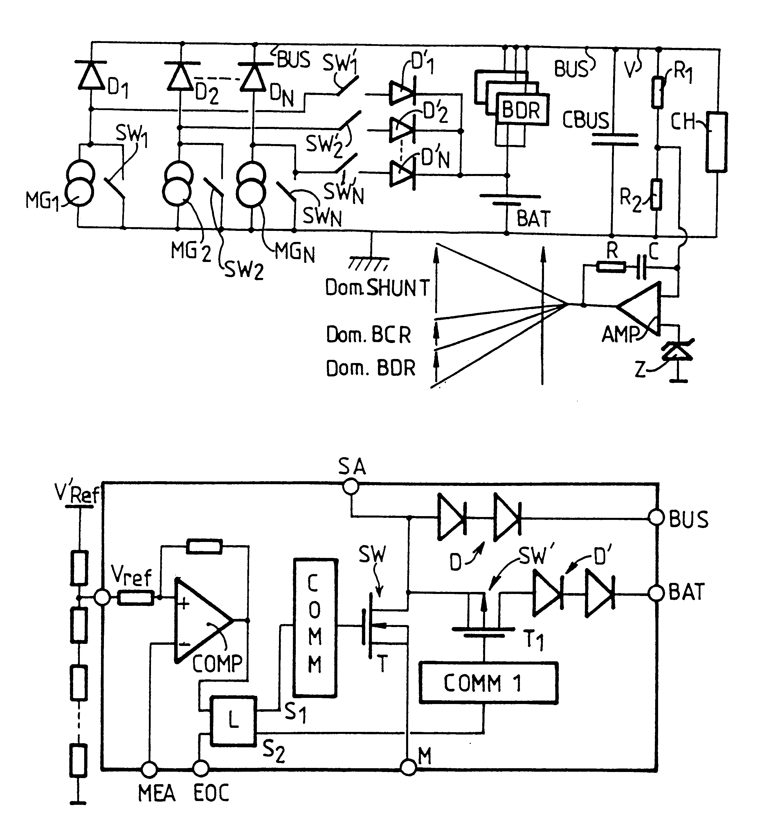
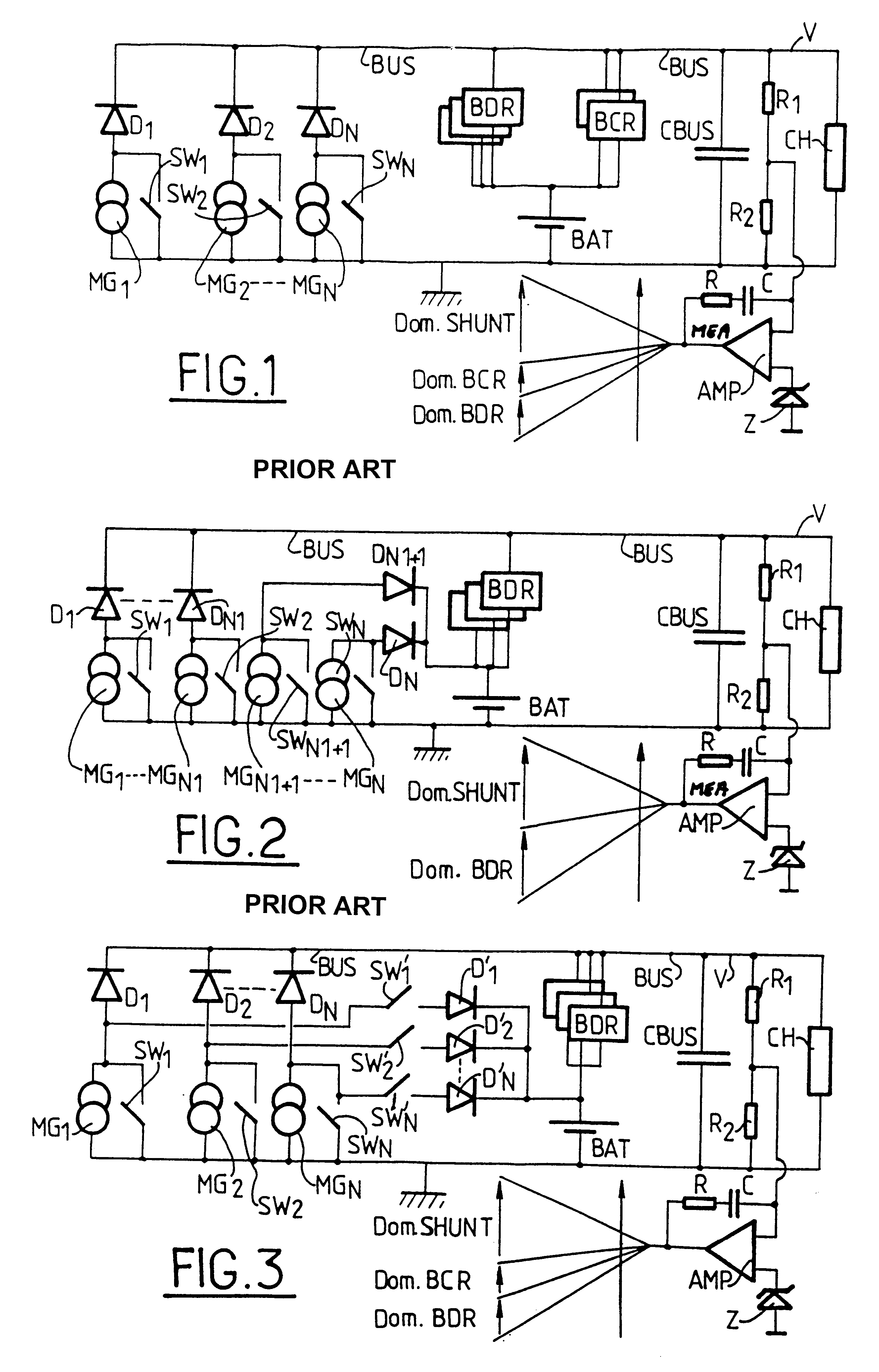
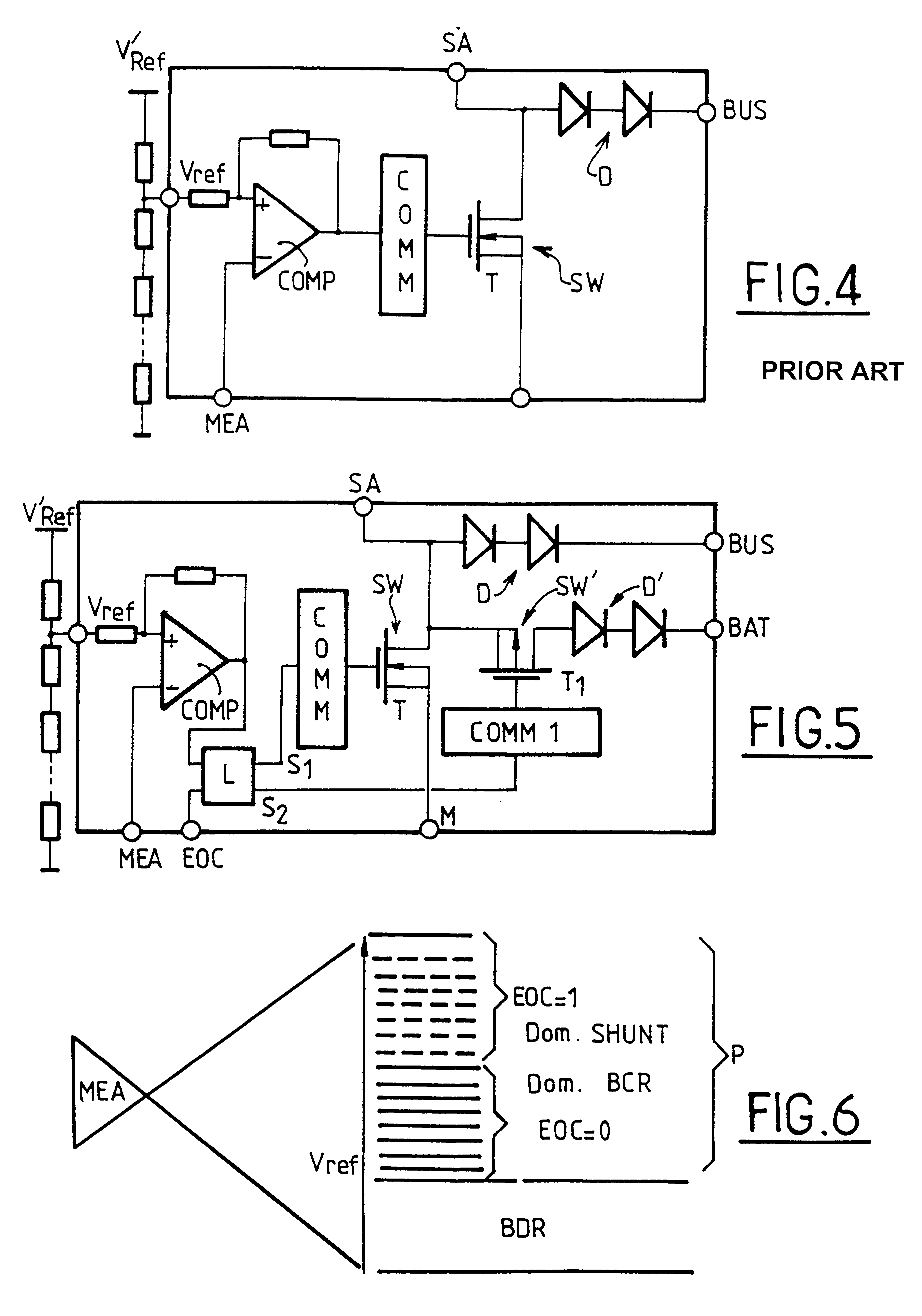
The topology shown in FIG. 1 which corresponds to the known three-domain concept, implements N generator module sections MG.sub.1, MG.sub.2, etc. MG.sub.N, each presenting in parallel a controlled shunt switch SW.sub.1, SW.sub.2, etc. SW.sub.N, and each module is coupled to a power supply bus BUS via a respective forwardly-conductive diode D.sub.1, D.sub.2, etc. D.sub.N. An electrical energy storage unit BAT comprising at least one battery is coupled to the bus BUS via a battery charge regulator BCR in parallel with a battery discharge regulator BDR. The bus BUS includes, in conventional manner, a capacitive element CBUS, and the bus BUS powers a load CH. A mean error signal MEA concerning the voltage V of the bus BUS compared with a reference voltage as given by a zener diode Z is delivered at the outlet of an integrating amplifier AMP. Depending on how high or low the signal MEA happens to be, the system operates either in a shunt domain (higher values) or in a battery charging do...


PUM


Abstract

A device for generating electrical energy for a power supply bus connected to a load. The device includes an electrical energy storage unit having at least one battery, a solar energy generator presenting a plurality of modules, a regulator for controlling discharging of the storage unit to power the bus, and for each module, a three-state control device. The device also includes a control unit causing the control devices to take up one of their three states. Each three-state control device has a first state in which current from the module powers the bus, a second state in which current from module powers the storage unit, and a third state in which the module is short-circuited.

Description

The present invention relates to a device for generating electrical energy for a power supply bus, in particular a regulated bus of the kind used on board satellites.Such devices provide the best results for a minimum area of solar sensor and a minimum mass of batteries. Such regulated buses at 50 V or indeed at 100 V are used for geostationary telecommunications satellites and are presently implemented for constellations of satellites such as SKYBRIDGE or indeed CELESTRI / TELEDESIC.At present, there exist several known architectures for powering a bus from a solar energy generator and from an electrical energy storage unit comprising one or more batteries.The first concept implements three operating domains, specifically shunt control of excess solar energy generated at a given instant (via a short circuit), charging the energy storage unit, and discharging the energy storage unit. The operating domains are controlled by a control loop which governs the transition between modes and ...

Claims


Application Information

Patent Timeline
IPC IPC(8): H02J7/35
CPCB64G1/428B64G1/443H01M10/44H01M10/465H02J7/35B64G1/1007B64G1/1085Y10S323/909Y02E60/10
Inventor PEROL, PHILIPPE ALFREDOLSSON, DANHAINES, JAMES EDWARD
Owner EUROPEAN SPACE AGENCY
Learn More