Braking estimation device, anti-lock brake controller, and braking pressure controller

a technology of estimation device and braking pressure controller, which is applied in the direction of fluid pressure measurement by mechanical elements, braking components, special data processing applications, etc., can solve the problems of increasing the cost of pressure sensors, and reducing the accuracy of braking

Inactive Publication Date: 2001-01-30
TOYOTA CENT RES & DEV LAB INC
View PDF24 Cites 61 Cited by
  • Summary
  • Abstract
  • Description
  • Claims
  • Application Information

AI Technical Summary

Problems solved by technology

However, the pressure sensors are comparatively expensive, and attachment of the pressure sensors to each wheel cylinders is difficult in terms of cost.
However, in many widely-available ABS controllers, a pressure sensor is not attached even to the master cylinder.
Therefore, even the foregoing wheel cylinder estimation technique that requires the attachment of a pressure sensor to only the master cylinder still adds to the cost.
Further, there is needed a remedy for sensor failures in order to ensure the reliability of the pressure sensor, which also adds to the cost.
However, the statistical property of the ext

Method used


Image

  • Braking estimation device, anti-lock brake controller, and braking pressure controller
  • Braking estimation device, anti-lock brake controller, and braking pressure controller
  • Braking estimation device, anti-lock brake controller, and braking pressure controller

Examples


first embodiment

An example of application of the present invention to detection of a fault in an active suspension control system in a vehicle will now be described as a first embodiment.

FIG. 6 shows a specific example of a dynamic system 10 shown in FIG. 1 to be examined in the first embodiment. This dynamic system 10 represents a vibration model of a single wheel suspension unit of the vehicle. In the drawing, a wheel 41 is represented by a combination of an unsprung mass section expressed by a parameter m1 and a spring section of the wheel (or tire) expressed by a spring constant k1. Reference numeral 42 designates a vehicle body having a spring constant m2; 46 designates a gas spring having a spring constant k2; 48 designates a damper having a damping constant Dm; and 56 designates the amount of displacement with reference to the road surface. Further, reference numeral 52 designates unsprung displacement represented by a variable x1; 50 designates sprung displacement represented by a variable ...

second embodiment

A second embodiment of the present invention will now be described.

FIG. 10 shows a specific example of the dynamic system 10 to be examined in the second embodiment which comprises an active suspension system and wheels. The members corresponding to those shown in FIG. 6 are assigned the same reference numerals, and their explanations will be omitted here.

Such an active suspension system is usually provided with a pressure sensor 60a as a member required for active control of the suspension system. The pressure sensor 60a is provided in the control force generator 16 so as to be able to measure the active control force "f." Further, acceleration sensors 60b and 60c are provided for detecting an anomaly in the air pressure in the tire. Both the acceleration sensors 60b and 60c are provided at the upper end and at the lower end of the suspension spring, respectively, so as to be able to detect the acceleration of vertical vibrations.

In such a dynamic system 10, the equation of state r...

third embodiment

FIG. 12 shows the suspension system 10 comprising a conventional suspension (not an active suspension) and wheels. In the suspension system 10, the wheel 41 is represented by combination of an unsprung mass section expressed by a parameter m1 and a spring section of the tire expressed by a spring constant k1. Reference numeral 42 designates a vehicle body having a sprung mass m2; 46 designates a spring having a spring constant k2; 48 designates a damper having damping constant Dm; 56 designates displacement with reference to the road surface; 52 designates unsprung displacement expressed by variation x1; 50 designates sprung displacement represented by variation x2; and 54 designates relative displacement (x1-x2) represented by variable "y." Even in this dynamic system 10, as in the previous embodiments, the acceleration sensors 60b and 60c for detecting vertical vibrations of the wheel are provided in the respective sprung and unsprung sections.

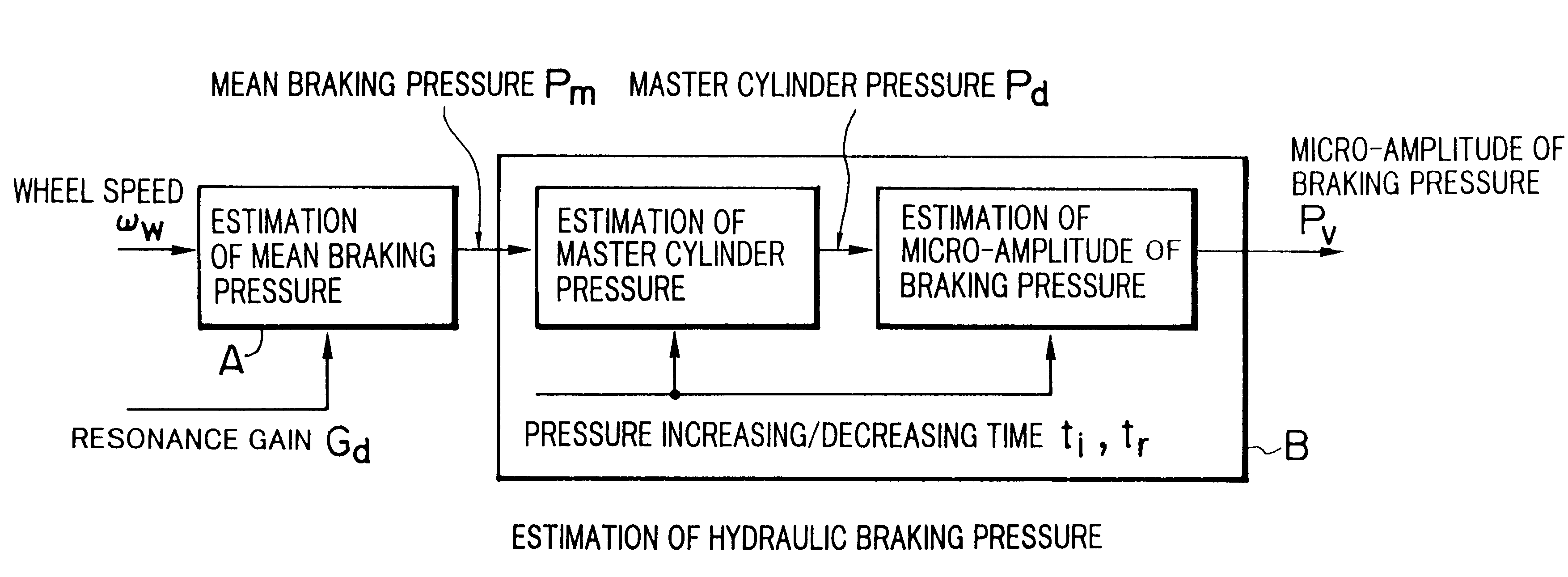
In the third embodiment, the braking ...


PUM


Abstract

An apparatus for diagnosing a fault in a dynamic system includes a controller which controls the dynamic system through use of a control input signal and vibrates the dynamic system through use of an vibration signal irrelevant to the internal state quantity of the dynamic system; an observer for estimating, on the basis of a response output from the vibration dynamic system, total disturbance which is a sum of an internal disturbance vector stemming from a fault in the dynamic system and a vibration disturbance vector occurring in the dynamic system through vibration; a correlation calculation unit which calculates cross-correlation between the thus-estimated total disturbance and the internal state quantity of the dynamic system and separates a component related to the internal disturbance from the total disturbance; and a diagnostic unit for diagnosing a fault in the dynamic system on the basis of the thus-separated component related to the internal disturbance. Since the dynamic system is vibrated, the response output can be increased even when there exists small external disturbance. As a result, a fault or a variation in air pressure in a tire can be highly accurately diagnosed.

Description

1. Field of the InventionThe present invention relates to a diagnostic apparatus for a dynamic system, and more particularly, to an apparatus for very accurately diagnosing faults in a dynamic system, the air pressure of a tire, and conditions around the tire by vibrating the dynamic system through use of vibration means provided in the diagnostic apparatus and on the basis of internal disturbance caused by a fault in the thus-vibrated dynamic system even in a case where the amount of external disturbance is small.Further, the present invention relates to a braking pressure estimation device which estimates master cylinder pressure, mean braking pressure, and a micro-vibration component in the braking pressure on the basis of wheel speed information and without use of a braking pressure sensor, by taking note of the gain characteristics of a wheel speed and the braking pressure in a case where the braking pressure is minutely vibrated at a resonance frequency of a vibration system c...

Claims


Application Information

Patent Timeline
IPC IPC(8): B60T8/88
CPCB60T8/885B60T2270/413
Inventor SUGAI, MASARUASANO, KATSUHIROUMENO, TAKAJIONO, EIICHIYAMAGUCHI, HIROYUKI
Owner TOYOTA CENT RES & DEV LAB INC
Why Eureka
Try Eureka