Protection circuit for a boost power converter

a protection circuit and converter technology, applied in the direction of electric variable regulation, process and machine control, instruments, etc., can solve the problems of overheating of the switching element, destroying voltage-sensitive loads, and not providing sufficient power to the outpu

Inactive Publication Date: 2001-02-06
SEMICON COMPONENTS IND LLC
View PDF17 Cites 147 Cited by
  • Summary
  • Abstract
  • Description
  • Claims
  • Application Information

AI Technical Summary

Problems solved by technology

Most power supply specifications require protection against the following common occurrences: (1) shorts to ground or overload currents, which can destroy the switching element and series-pass element; (2) output over-voltage, which can destroy voltage-sensitive loads; and (3) input under-voltage, which can not deliver sufficient power to the output and poten...

Method used


Image

  • Protection circuit for a boost power converter
  • Protection circuit for a boost power converter
  • Protection circuit for a boost power converter

Examples


Embodiment Construction

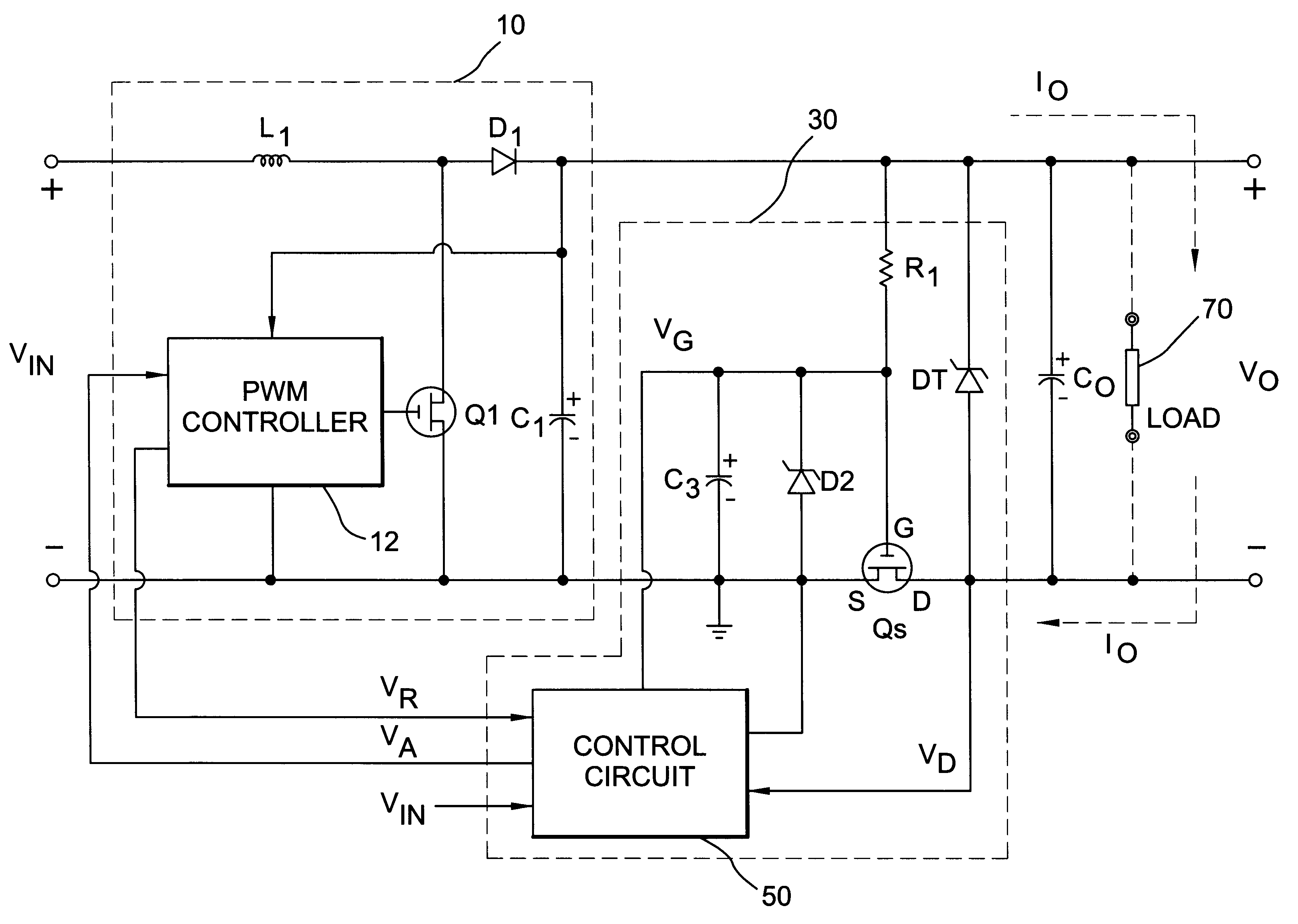
The present invention is a protection circuit of a boost converter, which provides input under-voltage, output over-voltage, and output over-current protection.

FIG. 3. is a circuit diagram showing a preferred embodiment of the present invention. The protection circuit 30 includes a power MOSFET Qs connected in series between the ground of a boost converter 10 and the ground of a load 70. The source of the MOSFET Qs is linked to the ground of the boost converter 10, and the drain of the MOSFET Qs is connected to the ground of the load 70. A resistor R1 is connected from the positive output of the boost converter 10 to the gate of the MOSFET Qs for driving the MOSFET Qs on. A capacitor C3 is connected between the gate and source of MOSFET Qs. The capacitor C3 acts with the resistor R1 to provide a slow slew-rate for powering on the MOSFET Qs and to soft-start the load. A zener diode D2 is connected in parallel with the capacitor C3 to clamp the gate-voltage of the MOSFET Qs under its ...


PUM


Abstract

A protection circuit for a boost power converter provides input under-voltage protection and output over-voltage and over-current protection. The protection circuit includes a control power MOSFET connected in series between the ground of the boost power converter and the ground of the load. The arrangement of the circuit makes it easy to drive the gate of an N-channel power MOSFET and is ideal for current-limiting control, which utilizes the Rds-on of the MOSFET as a current sensing element. Neither a specific gate-driver nor a current sensing resistor is required, and thus high efficiency can be achieved. Furthermore, the slow slew-rate at the gate of the MOSFET provides a soft-start to the load. The protection circuit includes a temperature compensation circuitry to offset the variation of the Rds-on. A time delay circuit prevents the switching elements and protection elements from overload damage.

Description

1. Field of InventionThe present invention relates to boost power converters ("boost converters"), and more particularly to a protection circuit of a boost converter which provides under-voltage, over-voltage, and over-current protection.2. Background of the InventionA boost converter is typically used to produce a higher regulated voltage from a lower unregulated voltage, including power factor correction (PFC) and DC-to-DC boost regulation. Several publications explain the operation of boost converters, such as: (a) Keith H. Billings, "Switchmode Power Supply Handbook," McGraw-Hill Book Co., p2.162-p2.166; and (b) Abraham I. Pressman, "Switching Power Supply Design," McGraw-Hill Book Co., p24-p35.An example of a conventional boost converter 10 is shown in FIG. 1. The boost converter 10 includes a transistor Q1, inductor L1, diode D1, capacitor C1 and a PWM controller 12. The inductor L1 is connected in series with VIN and the transistor Q1. When the transistor Q1 is on for a time ...

Claims


Application Information

Patent Timeline
IPC IPC(8): H02M1/00H02M3/156H02M3/04H02M1/32
CPCH02M1/32H02M3/158
Inventor YANG, TA-YUNG
Owner SEMICON COMPONENTS IND LLC
Why Eureka
Try Eureka