Automatic closer of pop-up door of vehicle

a pop-up door and automatic technology, applied in the direction of doors, roofs, wing accessories, etc., can solve the problems of inability of the wire-winding device to wind the connection wire in a short period of time, the rear door is swung downward against the press-up force of the damper, and the door is closed

Inactive Publication Date: 2001-02-13
TOYOTA SHATAI KK
View PDF14 Cites 73 Cited by
  • Summary
  • Abstract
  • Description
  • Claims
  • Application Information

AI Technical Summary

Problems solved by technology

In addition, great force is required to swing the rear door downward against the press-up force of the damper.
This kind of automatic closer has problems in that the wire is sandwiched between the rear door and the periphery of the rear opening of the vehicle body while the automatic closer is operating; that the driving motor for driving the wire-winding device must be large to apply sufficient tension to the wire; and that the rear door is closed at varying speeds.
When the door pivots downward rapidly by its own weight immediately before the door is completely closed, the wire-winding device is incapable of winding the connection wire in a short period of time because the wire-winding device winds it at a constant speed.
Thus, the connection wire will be loose.

Method used


Image

  • Automatic closer of pop-up door of vehicle
  • Automatic closer of pop-up door of vehicle
  • Automatic closer of pop-up door of vehicle

Examples


second embodiment

In a second preferred embodiment: of the present invention, the switch 12 for closing the rear door (D) of the first embodiment is not used. FIG. 10 shows the pulley 6 of the second embodiment. A ring plate 68 made of black resin constituting a rotation detection means is fixed to the periphery of the pulley 6. A large number of transparent holes 681 are in the periphery of the ring plate 68 at regular intervals. A pair of projections 691 and 692 spaced at a certain interval vertically are at the front of an optical sensor 69 to sandwich the periphery of the ring plate 68 therebetween. When a transparent hole 681 is coincident with the projections 691 and 692, light emitted by a light emitting element inside the projection 691 passes through the transparent hole 681, thus illuminating a light receiving element inside the projection 692. The optical sensor 69 outputs pulse signals to an unshown motor control circuit each time the transparent hole 681 becomes coincident with the proje...

third embodiment

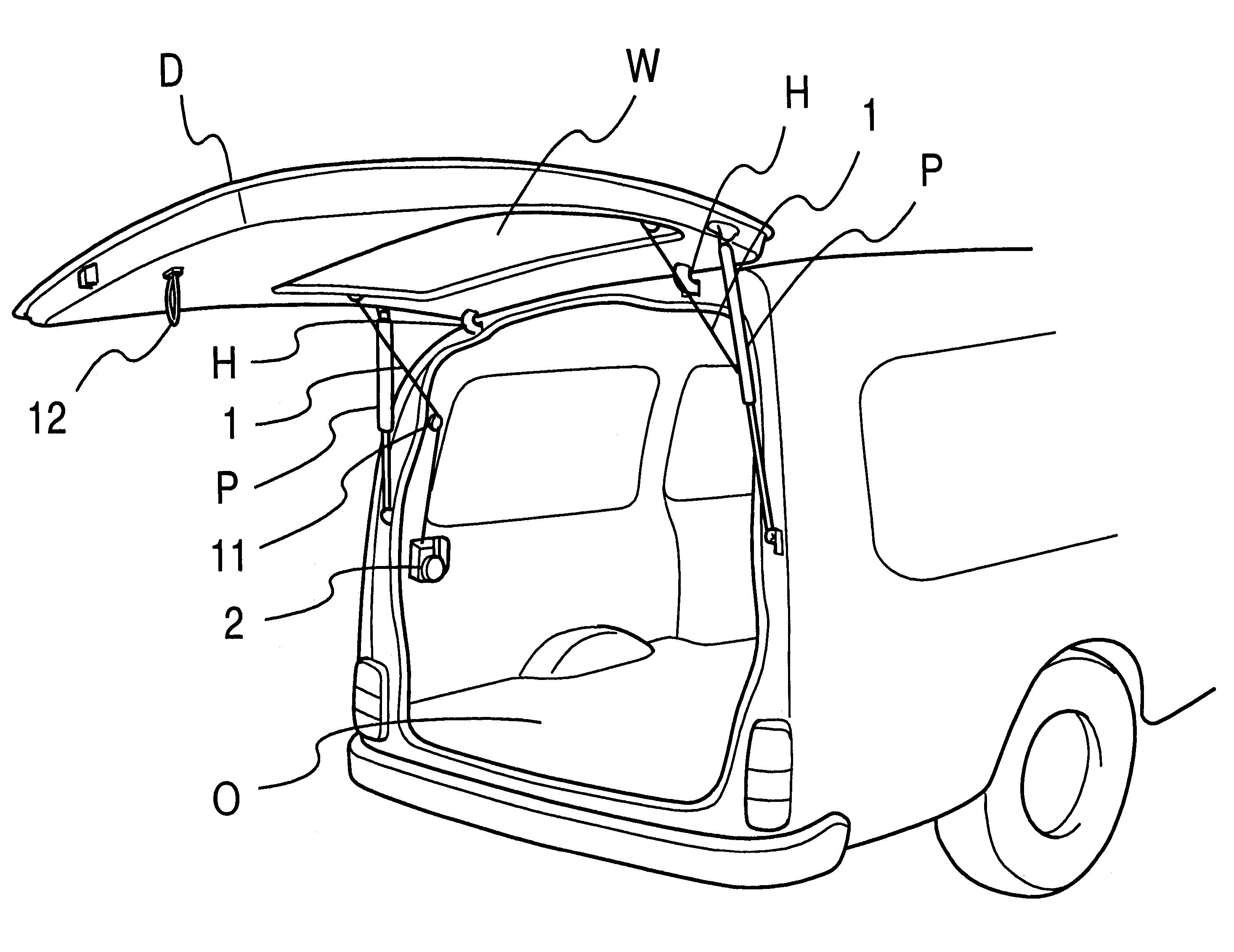
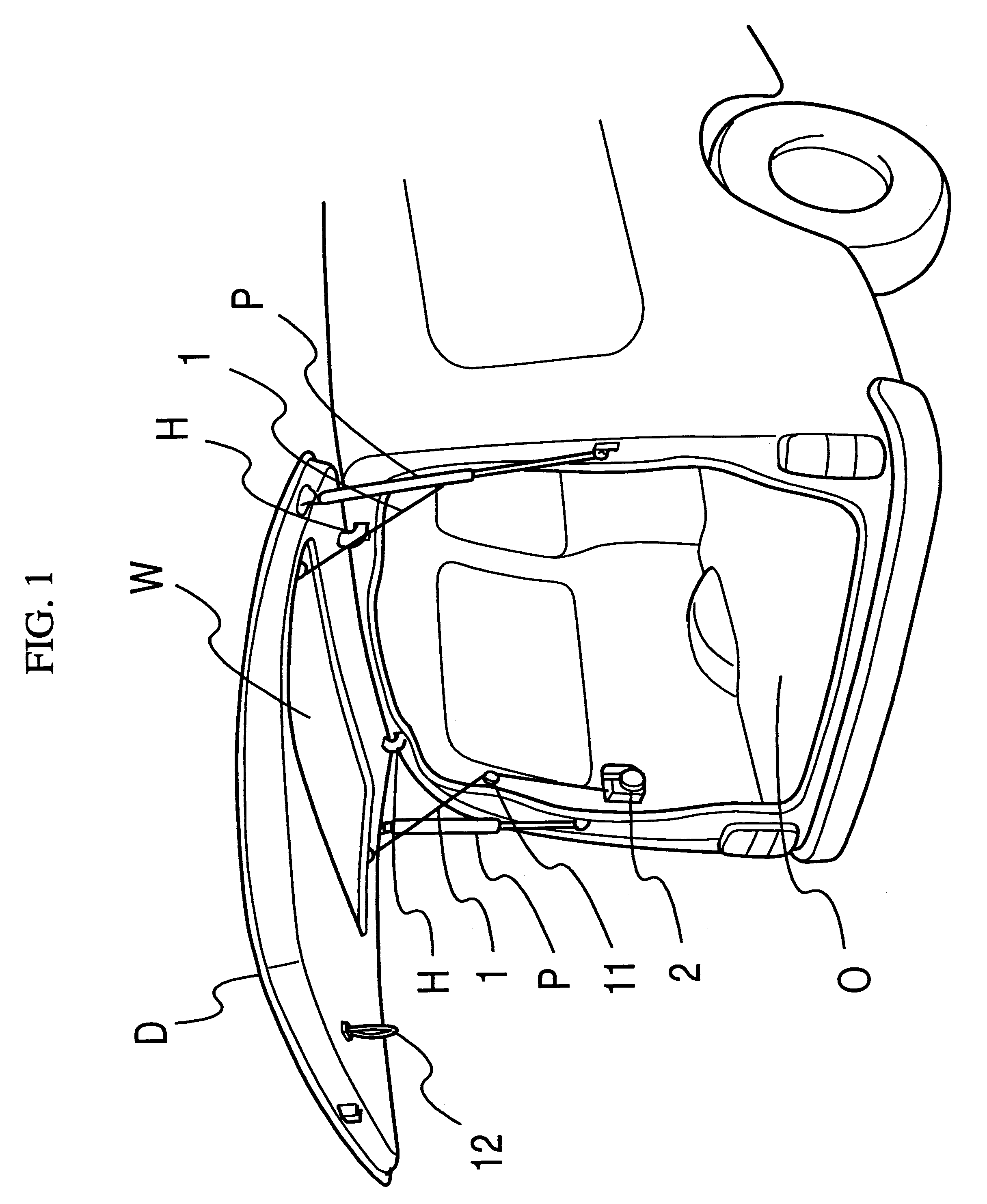
FIG. 11 shows a part of the connection wire 1 extending from the wire-connected portion of the rear door (D) to the guide roller 11 proximate to the edge of the rear opening (O) of the vehicle body according to a third preferred embodiment of the present invention. A coil spring 15 serving as a guide member is on a fixed bracket 14 for accommodating the connection wire 1 extending from the wire-winding device 2 (see FIG. 1) to the rear door (D). The coil spring 15 accommodating the connection wire 1 forms a certain angle with the linear locus (shown by double dot-dash line) of the connection wire 1 extending from the fixed bracket 14 to the guide roller 11, thus causing the connection wire 1 to greatly extend sideways. It is preferable that the coil spring 15 extends away from the periphery of the rear opening (O). The construction of winding the connection wire 1 is similar to that of the first embodiment.

When the rear door (D) is automatically closed, a tensile force is applied to...

fourth embodiment

In a fourth preferred embodiment of the present invention, the coil spring 15 is installed at a position different from that of the third embodiment, as shown in FIG. 13. FIG. 13 shows the connection wire 1 extending from the guide roller 11 on the rear part of the vehicle body proximate to the periphery of the rear opening (O) to the wire-winding device 2. The coil spring 15 accommodating the connection wire 1 and the guide roller 11 are held together as a unit. The coil spring 15 forms a certain angle with the linear locus (shown by the double dot-dash line) of the connection wire 1 extending to the wire-winding device 2, thus causing the connection wire 1 to greatly extend sideways. It is preferable that the coil spring 15 extends outward and sideways from the periphery of the rear opening (O). The construction of winding the connection wire 1 is similar to that of the first embodiment.

When the rear door (D) is automatically closed by the driving motor 21 (see FIG. 2), a tensile ...


PUM


Abstract

A connection wire is connected to a part of a rear door popped up in a door-opening direction by an urging force. A pulley rotates responsive to a driving motor inside a wire-winding device to wind the connection wire thereon. In this manner, the rear door is automatically closed. The pulley is urged in a connection wire-winding direction by a power spring. A clutch is between the pulley and the driving motor. When the rear door is pressed by an operator's hands in a door-closing direction while the rear door is being closed, the pulley is rotated by the power spring, thus winding the connection wire thereon and preventing the connection wire from becoming loose. At this time, the connection between the pulley and the driving motor is cut off by the clutch. Thus, the pulley is rotated by the power spring freely and rapidly. In this manner, the rear door can be closed manually even while it is being closed automatically. Further, the connection wire can be prevented from becoming loose and from being sandwiched between the body of the vehicle and the periphery of a rear opening thereof.

Description

This application is related to Japanese Patent Application Nos. Hei 8-277036 and 8-277588, incorporated herein by reference.1. Field of the InventionThe present invention generally relates to an automatic closer of a pop-up door of a vehicle, and more particularly to an automatic closer for allowing the pop-up door of the vehicle to perform a closing operation by winding a connection wire.2. Description of Related ArtNormally, the upper end of a pop-up rear door of a van is connected to the upper side of the rear opening of the body by a hinge. A gas damper is at the upper side of the rear opening of the body to allow an operator to press the rear door upward using a reduced amount of force. Thus, after the upward movement of the rear door is started, the rear door is pressed upward by the extension force of the damper. When the rear door is popped up at the maximum angle, the lower edge of the rear door is so high that a short person must stretch up to grasp the lower edge of the r...

Claims


Application Information

Patent Timeline
Patent Type & Authority Patents(United States)
IPC IPC(8): B60J5/10E05F15/12E05F1/10E05F1/00E05F11/48
CPCE05F15/627E05F1/1091E05Y2201/216E05Y2201/234E05Y2201/41E05Y2201/416E05Y2201/434E05Y2201/654E05Y2201/664E05Y2201/672E05Y2600/458E05Y2800/114E05Y2900/546E05Y2400/337E05Y2201/422E05Y2201/482E05Y2600/13E05Y2800/00E05Y2201/214
Inventor KATO, KENJI
Owner TOYOTA SHATAI KK
Why Eureka
Try Eureka