Threaded actuator for positioning structure subjected to intense loads

a technology of thrust actuators and positioning structures, which is applied in the direction of dough shaping, manufacturing tools, applications, etc., can solve the problems of not positively ensuring against some compression of the supporting structure, and achieve the effect of increasing the set up time, accurate and repeatable preload positioning of the actuator

Inactive Publication Date: 2001-02-13
PFA
View PDF2 Cites 40 Cited by
  • Summary
  • Abstract
  • Description
  • Claims
  • Application Information

AI Technical Summary

Benefits of technology

The prior mold systems which incorporate the preloading of the actuator require onsite assembly and adjustment of the motor unit to establish a desired preload force on the actuator extendible member. Although highly satisfactory results have been obtained with the prior system, the set up time is increased and can require careful attention. The differential adjustment system as disclosed permits accurate setting of the position and preload, and is a particular advance in the technology of high intensity molding and die casting. In accordance with a further teaching, the system of this invention, as well as the prior art structure and systems, can be provided with an internal rod loading system within the structure of the threaded actuator and motor power unit.
In this aspect of the invention, a sleeve member is coupled to the rod and forms a stop member which engages a stop member on the motor unit, rather than a stop member on the mold unit or tool as such. The outer stop is a "limiting device" forming an integrated part of the motor unit itself. The load can be factory set and the stop on the mold itself eliminated. This provides for very accurate and repeatable preload positioning of the actuator.

Problems solved by technology

Thus, although very rigid members are used for supporting of a core and in the core as such, it cannot be assumed under all conditions and particularly large intense forces, that even the large preload does not positively insure against some compression of the supporting structure during a molding cycle in the presence of the intense loading.

Method used


Image

  • Threaded actuator for positioning structure subjected to intense loads
  • Threaded actuator for positioning structure subjected to intense loads
  • Threaded actuator for positioning structure subjected to intense loads

Examples


Embodiment Construction

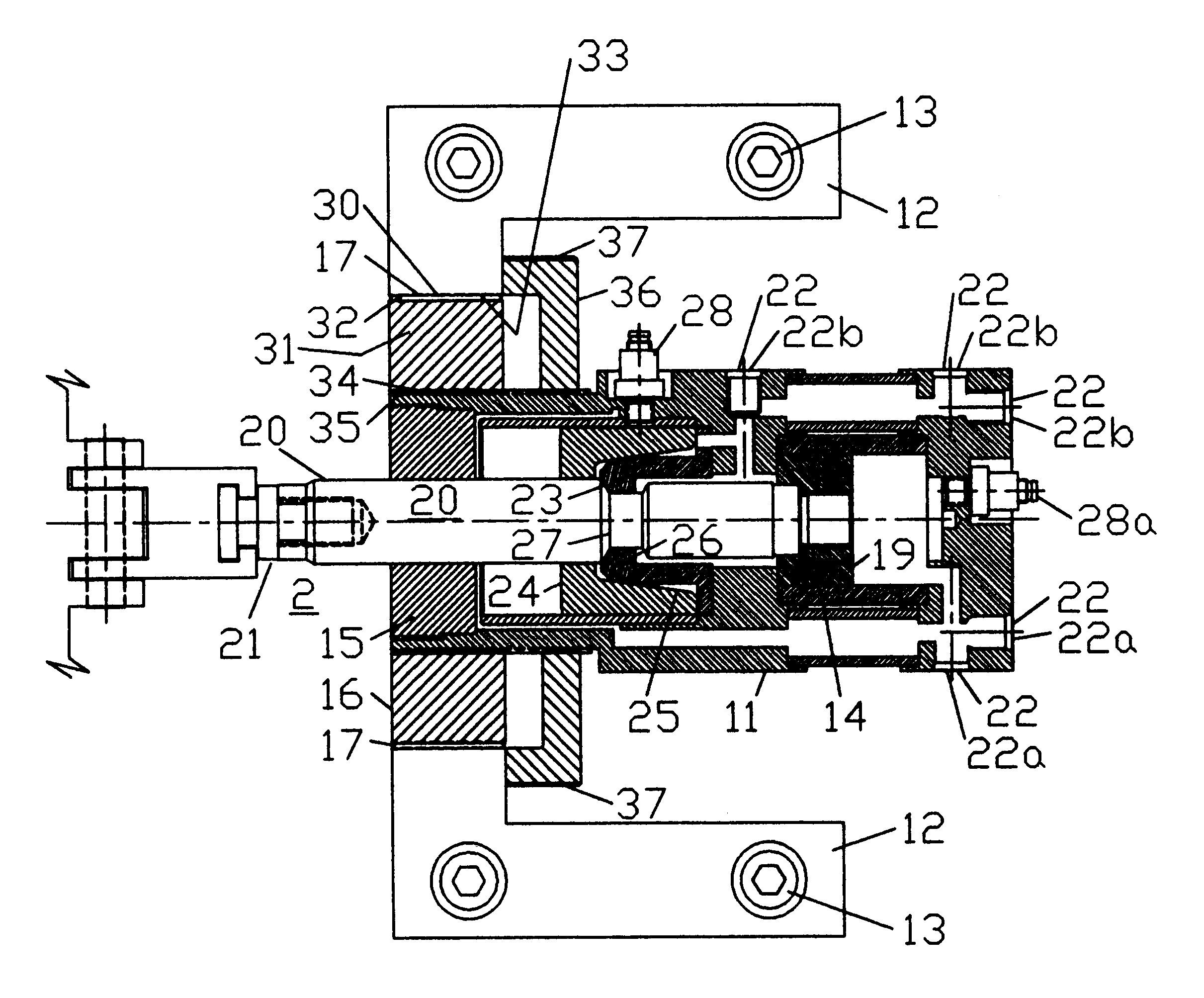
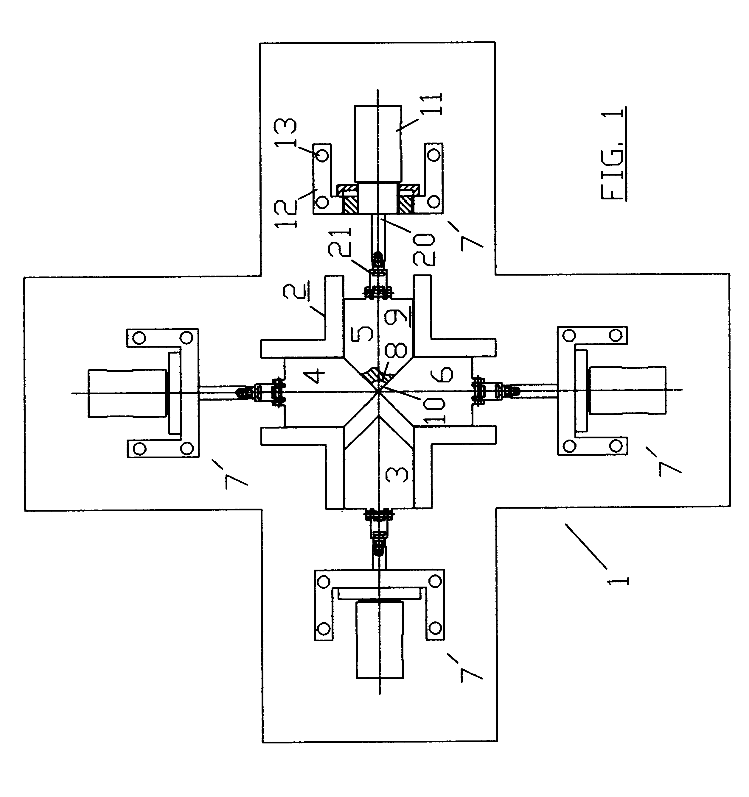
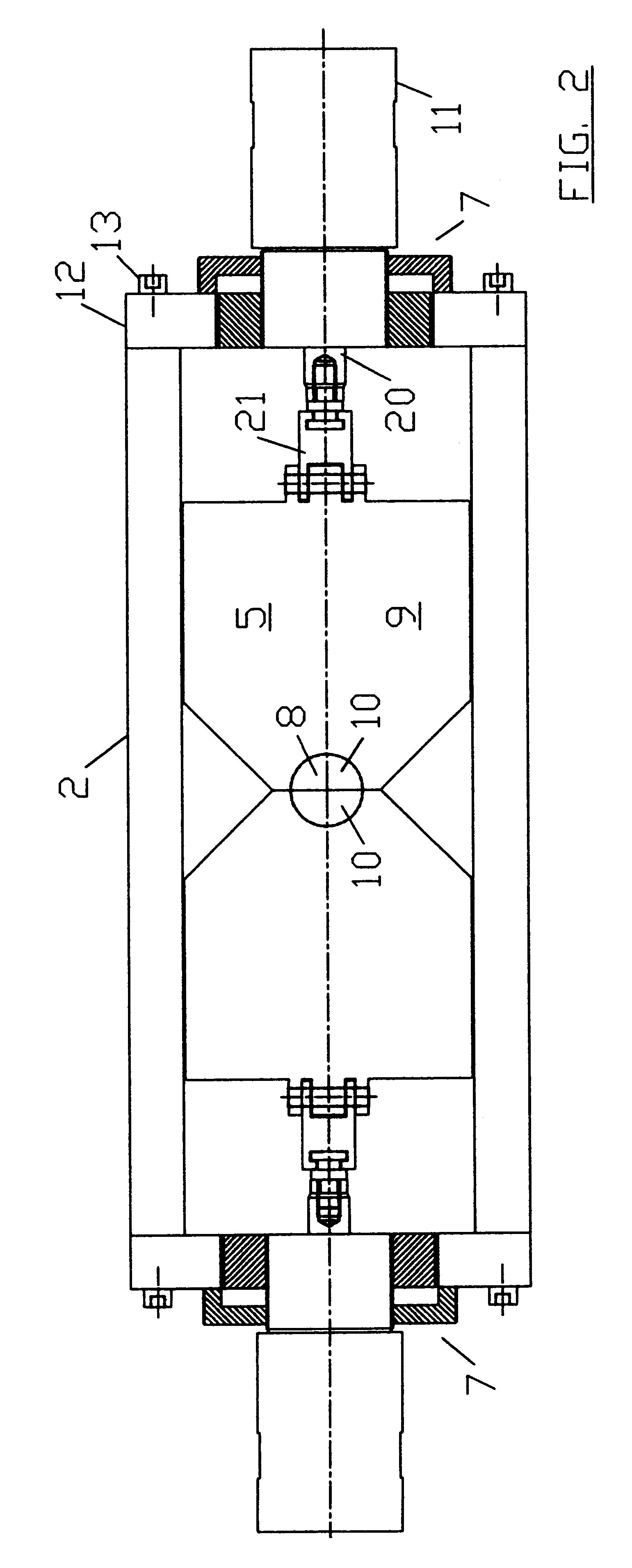
FIG. 1 is a plan view of a die casting apparatus illustrating an embodiment of the present invention. The apparatus includes a die casting mold 1 having an outer mold base 2. A cross-type opening is formed within the mold forming four slide-ways. Corresponding cores 3-6 are slidably mounted in the respective slide-way openings. Each is shown connected to similar threaded actuator unit 7 specially constructed as more fully described hereafter in accordance with a preferred embodiment of the present invention in order to precisely locate each of the cores 3-6 relative to each other. In the illustrated embodiment the inner location of the cores as shown in FIGS. 1 and 2 define a closed opening or cavity 8 defining the shape of a molded part. Each core 3-6 is shown as a substantial solid body 9, such as a square, cylinder or other shaped member. In the drawings, each core includes an innermost tapered end including a closed cavity opening 10 which, when combined with corresponding other...


PUM

PropertyMeasurementUnit
diameteraaaaaaaaaa
diameteraaaaaaaaaa
radial thicknessaaaaaaaaaa

Abstract

A threaded actuator is disclosed for positioning a core in a molding apparatus. The threaded actuator includes a hydraulic cylinder unit having a piston rod connected to the core for positioning thereof. The core is subjected to intense force during the molding process and this force is transmitted onto the piston rod and hydraulic cylinder unit and its support. The hydraulic cylinder has a threaded nose which is secured within a threaded opening in a support. A rotatable threaded connecting member is threaded between the threaded nose and the threaded opening of the support structure. The outer and inner threaded connections of the rotatable threaded connecting member are of different thread configurations to form a differential thread assembly. The configurations may differ either in pitch and/or in the handedness of the threads. The differential threaded assembly provides for relative positioning of the hydraulic cylinder unit and core relative to the mold. A preload system includes a wall on the cylinder and a wall on the rod for preloading of the locked rod and the supporting components. The hydraulic cylinder and the piston rod are formed with stop wall members which provide for controlled extension of the piston rod for preloading of the piston rod and the supporting structure. A locking unit provides for locking of the rod in an extended position.

Description

The present invention is directed to a threaded actuator for positioning a structure subjected to intense loads and forces, and particularly a motor driven extendible member positioned to receive and support an intense load.In various systems, an extendible member is accurately located between a rest position and an operative position. In the operative position, an intense force and load may be placed on the member. A typical application developed by the assignee of the present invention relates to injection mold and die casting systems in which a core of a mold body is positioned between an opened and closed position. For example, in a side-action system for molding and casting apparatus, one or more cores are slidably mounted with respect to each other within the mold body to open and close the mold. Each movable core is similarly mounted within a slide cavity and coupled to a threaded actuator secured to the mold base. The threaded actuator includes an hydraulic cylinder unit inc...

Claims


Application Information

Patent Timeline
Patent Type & Authority Patents(United States)
IPC IPC(8): B29C45/36B29C45/17B29C45/33F15B15/24F15B15/26F15B15/00B29C33/20
CPCB29C45/1775B29C45/332B29C45/36F15B15/24F15B15/261B29C33/20
Inventor SCANLAN, MARK R.
Owner PFA
Why Eureka
Try Eureka