Variable speed transmission

a transmission speed and variable technology, applied in the direction of gearing elements, belts/chains/gearrings, portability lifting, etc., can solve the problem of inability to reliably permit the flow of fluid, and achieve the effect of reliable and predictable manner

Inactive Publication Date: 2001-02-13
SCHAEFFLER TECH AG & CO KG
View PDF13 Cites 9 Cited by
  • Summary
  • Abstract
  • Description
  • Claims
  • Application Information

AI Technical Summary

Benefits of technology

An object of the invention is to provide a transmission of the above outlined character with a novel and improved sealing device

Problems solved by technology

A drawback of such standard sealing devices is that a lip seal is likely to be shifted and/or tilted and/or otherwise deformed and/or displaced so that it is incapable of reliably permitting the

Method used


Image

  • Variable speed transmission
  • Variable speed transmission
  • Variable speed transmission

Examples


Embodiment Construction

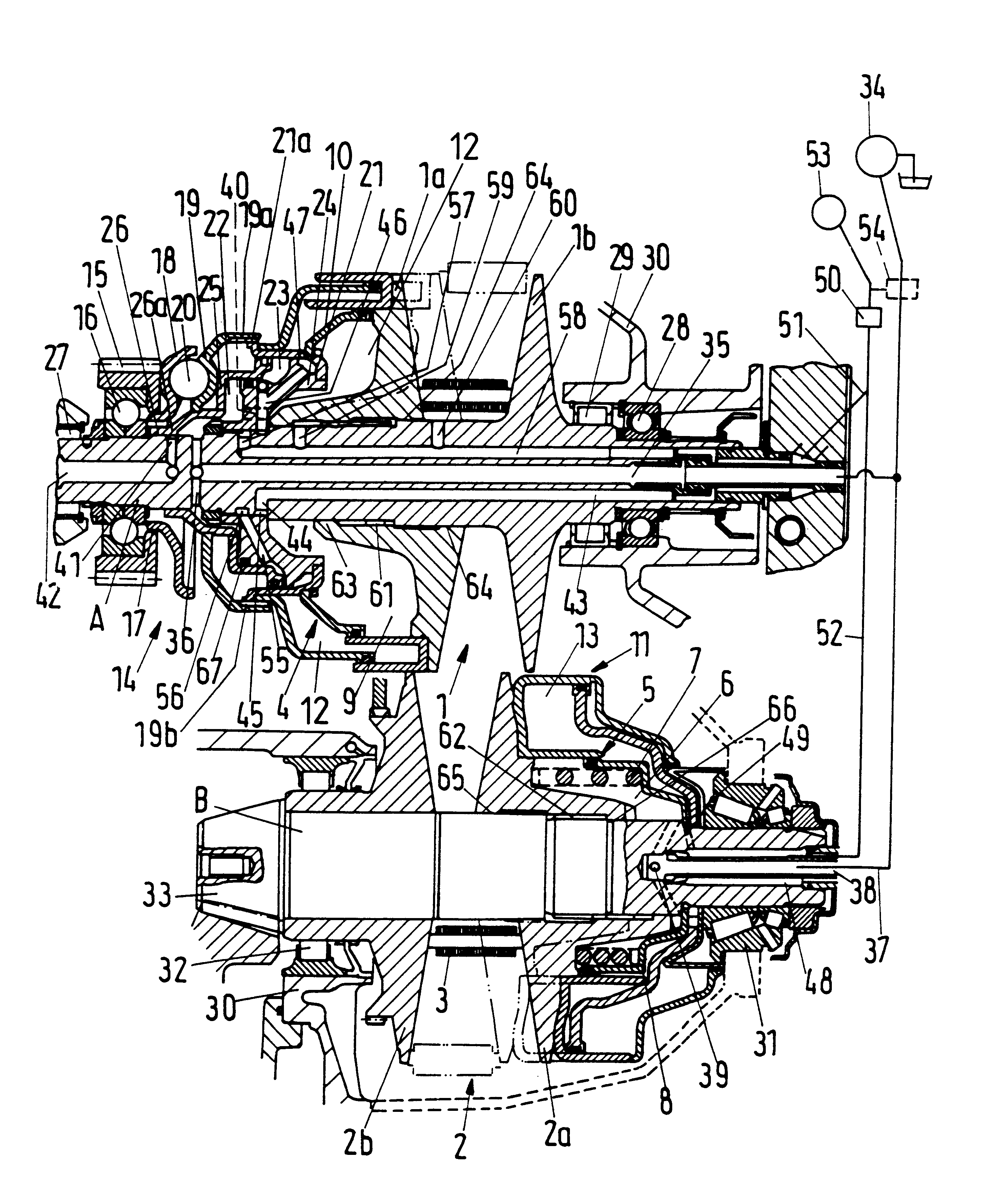
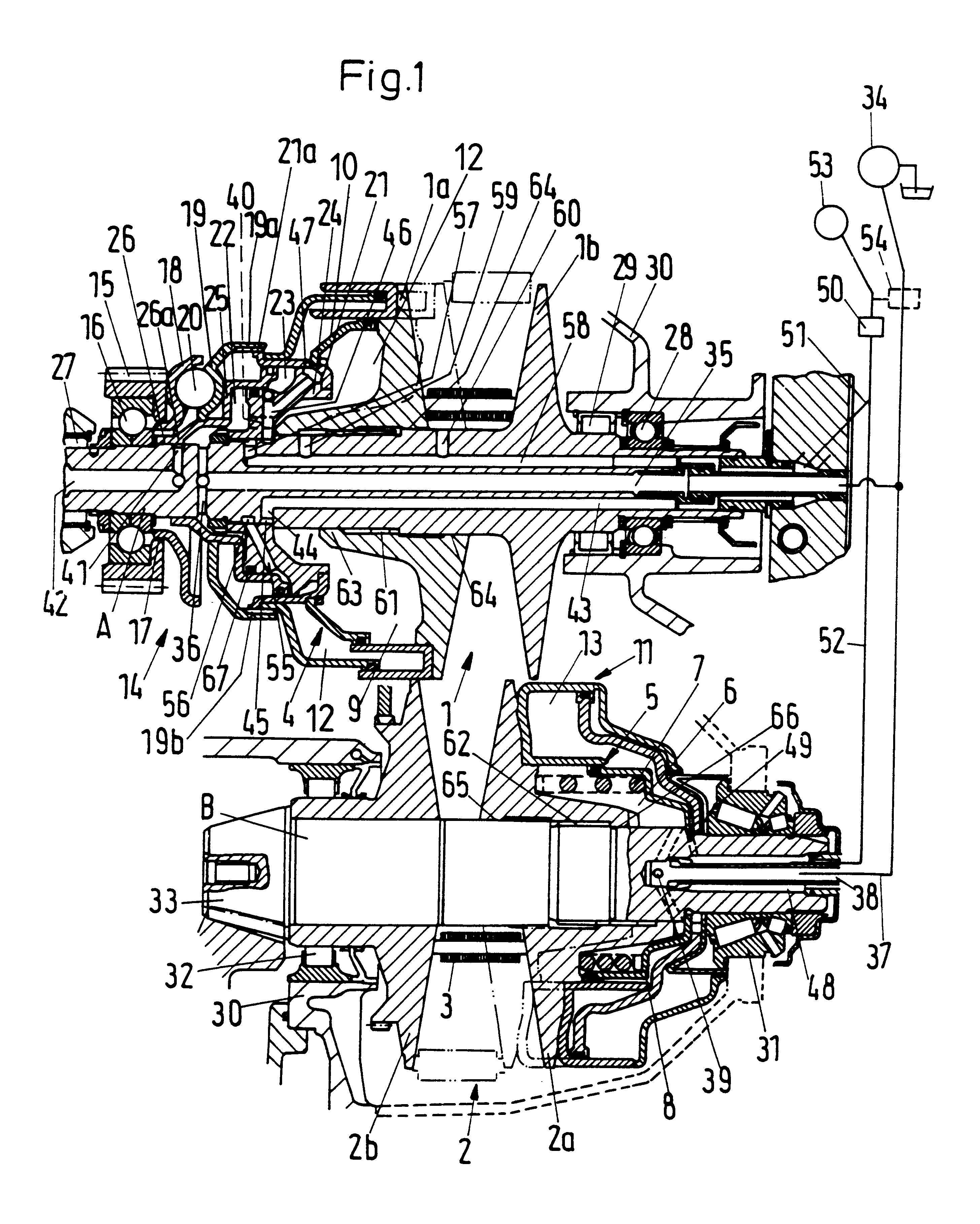
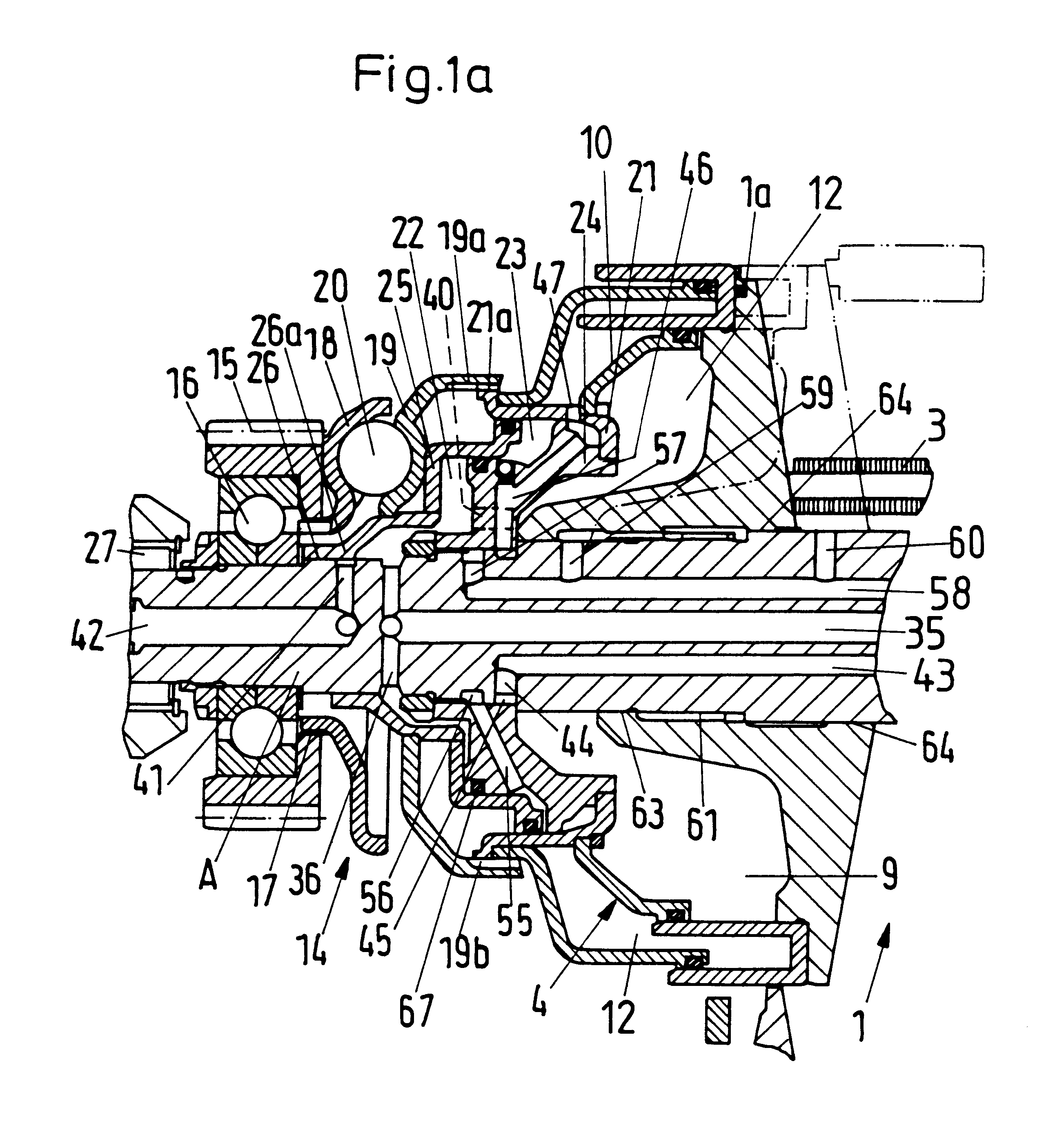
The structures shown in FIGS. 1, 1a, 2 and 3 are similar to those respectively shown in FIGS. 1, 1a, 2 and 3 of commonly owned U.S. Pat. No. 5,711,730 granted Jan. 27, 1998 to Oswald Friedmann and Armin Veil for "TORQUE MONITORING APPARATUS". The disclosures of this patent and of each and every other patent and / or (U.S. and / or foreign) patent application identified in this specification are incorporated herein by reference.

Referring first to FIGS. 1 and 1a, there is shown a portion of a power train which can be utilized in a motor vehicle and comprises a continuously or infinitely variable speed transmission having a first adjustable sheave 1, a second adjustable sheave 2, and an endless flexible chain 3 trained over and arranged to transmit torque between the two sheaves. The first sheave 1 is non-rotatably carried by the rotary output element A of a prime mover; the output element A can constitute the camshaft or the crankshaft of the internal combustion engine in the power train ...


PUM


Abstract

A continuously variable speed transmission with two adjustable sheaves and an endless chain trained over the sheaves has a torque transmitting and monitoring unit which is installed between a prime mover, such as the engine of a motor vehicle, and an axially movable flange of one of the sheaves. The monitoring unit has two annular plenum chambers which are sealed from each other while the ratio of the transmission is within a first range, and which communicate with each other when the ratio is within a second range. A check valve between the two chambers can employ a resilient annular seal having a U-shaped cross-sectional outline. A radially outer annular portion of the seal has a lip which normally bears against the internal surface of an annular member of the valve. The seal further comprises an annular radially inner portion, and the radially inner and/or outer portion of the seal can be provided with L-shaped, polygonal and/or otherwise configurated and/or profiled reliefs to further ensure proper operation of the valve.

Description

The invention relates to improvements in transmissions, and more particularly to improvements in continuously or infinitely variable transmissions of the type suitable for use in the power trains of motor vehicles.A transmission of the type to which the present invention pertains comprises a first adjustable sheave or pulley which can be driven, for example, by the output element (such as the crankshaft or the camshaft) of an internal combustion engine in the power train of an automotive vehicle, a second adjustable sheave or pulley which can transmit torque to a clutch or to a differential in the power train of the vehicle, and at least one endless flexible element (such as a belt or a chain and hereinafter referred to as chain) which is trained over and can transmit torque between the first and second sheaves. As a rule, each sheave comprises a first flange which is rigid (e.g., of one piece) with a shaft, and a second flange which cannot rotate relative to but is movable axially ...

Claims


Application Information

Patent Timeline
IPC IPC(8): F16H55/56F16H55/32F16H63/02F16H61/662F16H63/06F16H61/66F16H9/18
CPCF16H55/56F16H61/66272F16H63/065F16H61/662
Inventor FRIEDMANN, OSWALDWALTER, BERNHARD
Owner SCHAEFFLER TECH AG & CO KG
Why Eureka
Try Eureka