
Method for constructing reduced-order models of systems

a system and model technology, applied in the field of system model construction, can solve the problems of insufficiently addressing prior art, unable to articulate a systematic method for generating reduced-order models of vlsi interconnects, and exacerbate the possibility of signal delay and distortion

Inactive Publication Date: 2001-02-13
IBM CORP
View PDF4 Cites 22 Cited by
  • Summary
  • Abstract
  • Description
  • Claims
  • Application Information

AI Technical Summary

Problems solved by technology

High density circuit layouts and decreasing clock cycle times have amplified the effects of interconnect time delays and electromagnetic coupling in packaged electronic circuits, exacerbating the possibilities for signal delays and distortion.
We point out, by way of contrast and apposition, that the prior art has not adequately addressed this problem, and does not articulate a systematic method for generating reduced-order models of VLSI interconnects which include the effects of electromagnetic coupling and wire lengths.
That is, to an extent the prior art may somehow intersect with the situation outlined above, it must inherently respond to it by recourse to unsatisfactory ad hoc or heuristic expedients.

Method used


Image

  • Method for constructing reduced-order models of systems
  • Method for constructing reduced-order models of systems
  • Method for constructing reduced-order models of systems

Examples


Embodiment Construction

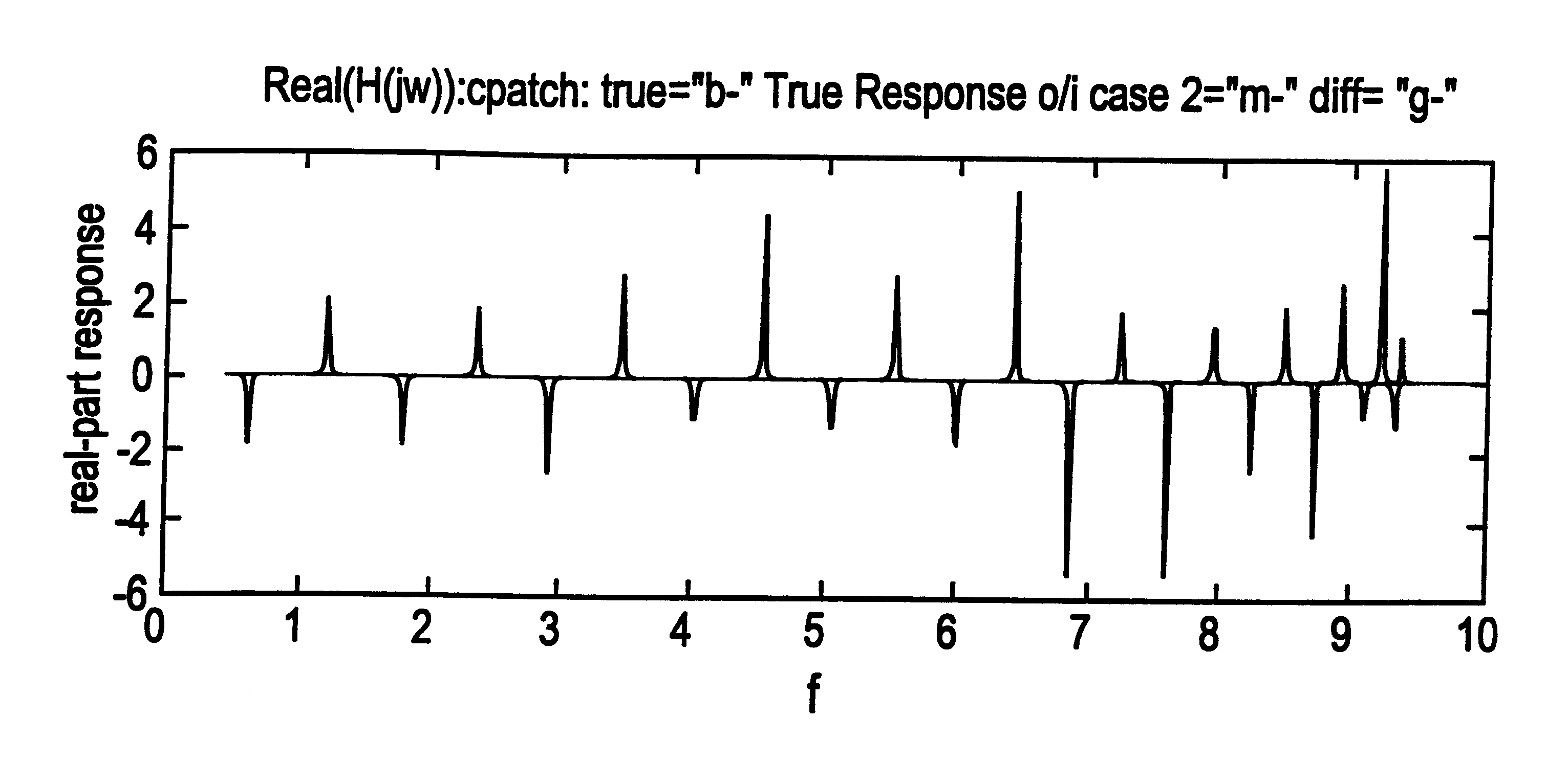
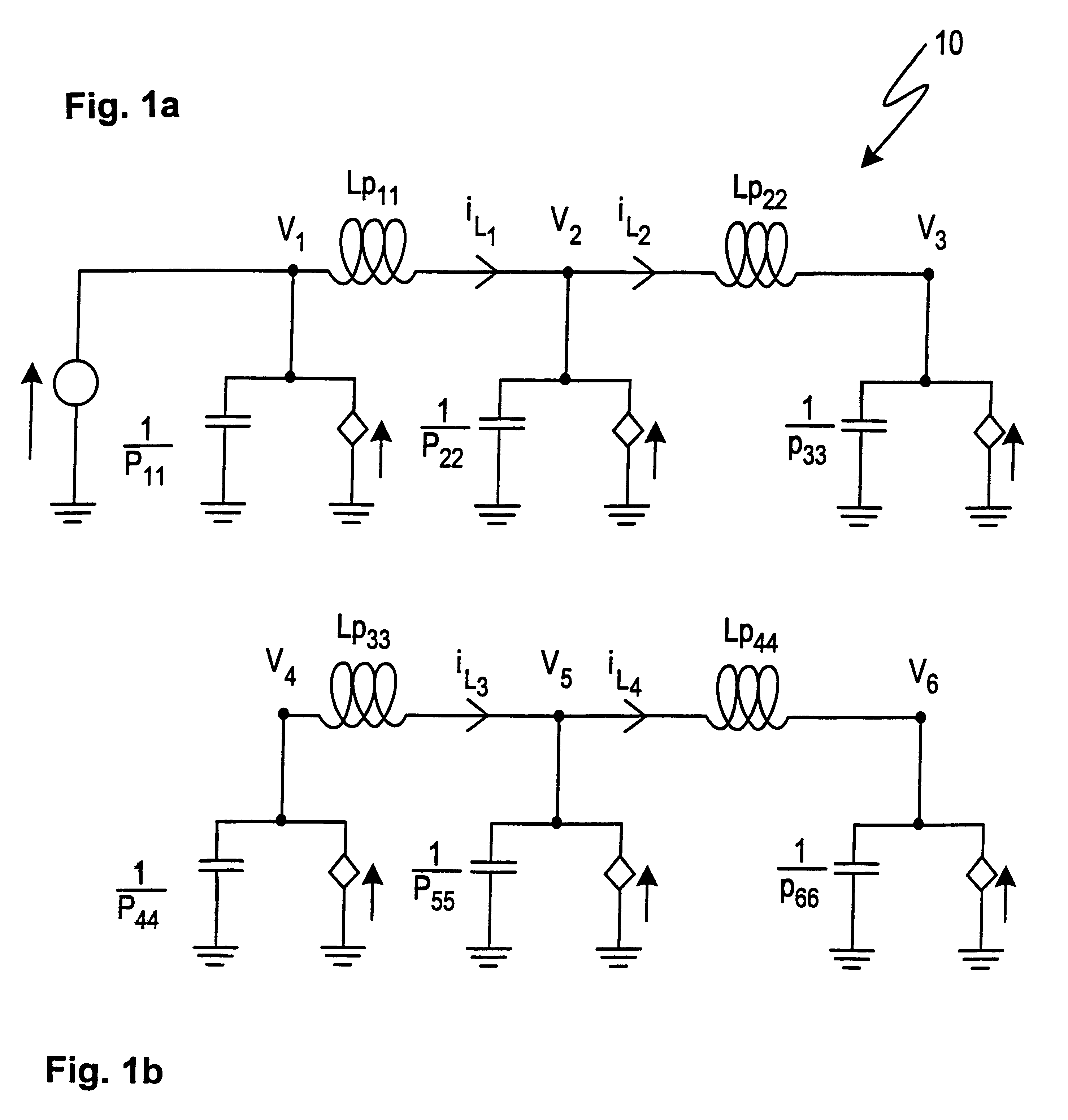
proceeds as follows. In section 1 we set forth the notation. In section 2 we review briefly PEEC formulations and give a schematic diagram and corresponding relationships for a simple PEEC example. In section 6 we use a larger version of this model to illustrate the proposed method. To motivate the invention, in section 3 we consider systems described by ordinary differential equations with no time delays.

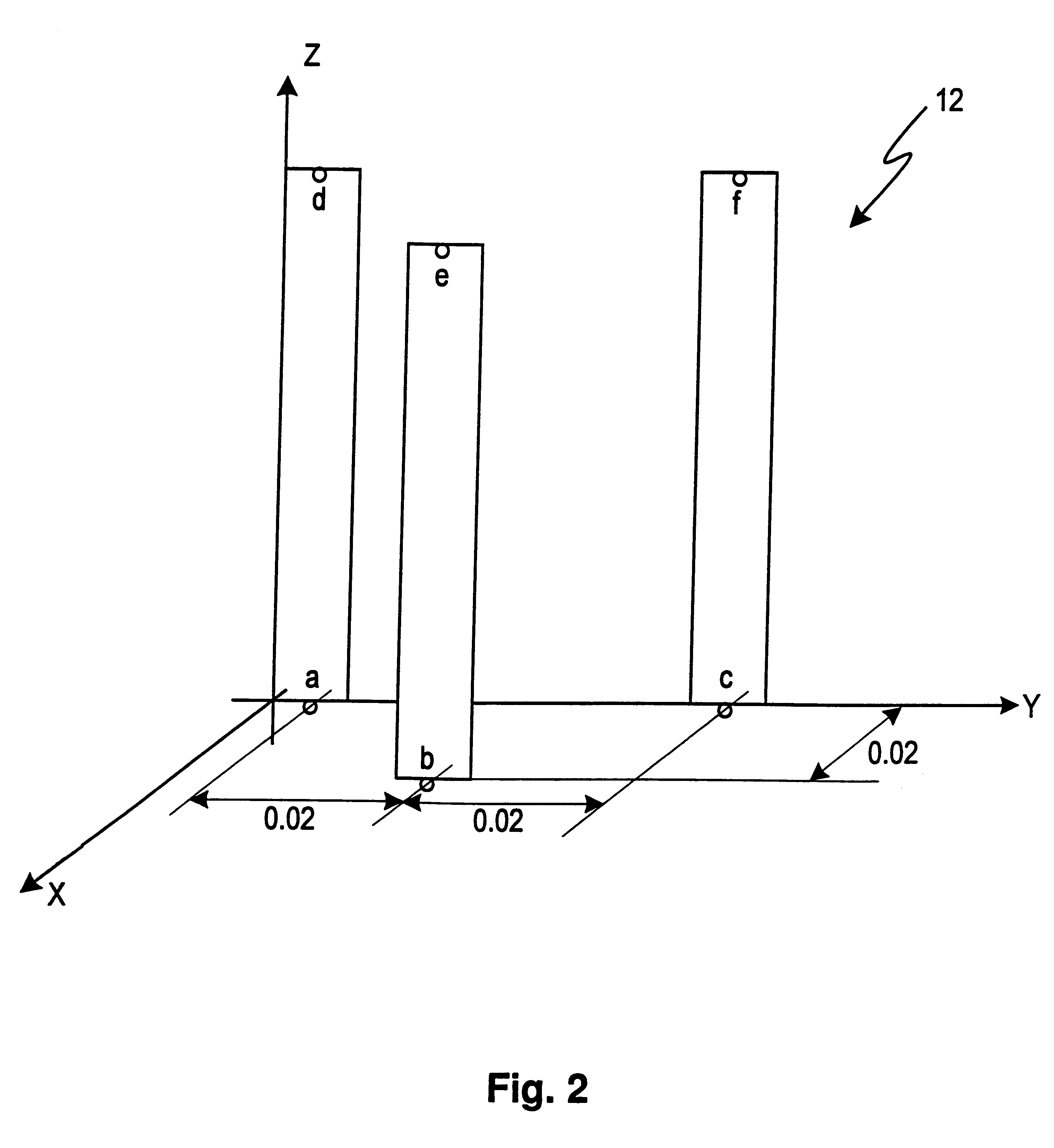
In section 4 we extend the discussion in section 3 to problems describable by linear time invariant systems of delay-differential equations. In section 5 we define a reduced-order modeling procedure for linear, time-invariant systems of delay-differential equations. The power of this approach is demonstrated in section 6 where we apply this procedure to Example 1 in FIG. 2, numeral 12. We use the following notation and definitions.

1 Notation

A=(a.sub.ij), 1.ltoreq.i,j.ltoreq.n, n.times.n matrix

A(s)=n.times.n matrix which is a function of parameter s

det(A(s)), determinant of A(s), s,...


PUM


Abstract

A method comprising a computational procedure for obtaining reduced-order models of partial element equivalent circuit (PEEC) models of very large scale integrated (VLSI) interconnects. The methodology is not limited to PEEC applications, and can be used for generating reduced-order models of other systems which can be modeled with linear, time-invariant systems of ordinary differential equations with time delays.

Description

This invention relates to a novel method for creating reduced-order models of various types of physical systems describable as linear circuit models with time delays.INTRODUCTION OF THE INVENTIONOur motivation and methodology for the present invention are informed by an illustrative situation which centers on models for VLSI interconnects. High density circuit layouts and decreasing clock cycle times have amplified the effects of interconnect time delays and electromagnetic coupling in packaged electronic circuits, exacerbating the possibilities for signal delays and distortion. Simulation software for analyzing the performance of circuit packages requires reduced-order models of well-chosen subsets of the circuits in the package. PEEC models for the VLSI interconnects in the package are formulated as linear circuit models with time delays and comprise one large subset which requires model reduction.With respect to the aforementioned package simulation models, it is necessary to cre...

Claims


Application Information

Patent Timeline
Patent Type & Authority Patents(United States)
IPC IPC(8): G06F17/50
CPCG06F17/5036G06F30/367
Inventor CULLUM, JANE GRACE KEHOERUEHLI, ALBERT EMIL
Owner IBM CORP
Learn More