Self-reinforcing friction clutch

Inactive Publication Date: 2001-02-20
MANNESMANN SACHS AG
View PDF20 Cites 20 Cited by
  • Summary
  • Abstract
  • Description
  • Claims
  • Application Information

AI Technical Summary

Problems solved by technology

If the internal combustion engine fails to run smoothly--a characteristic of the internal combustion engines which in design terms is impossible to rule out--the resulting torque fluctuations and torque peaks, which would otherwise lead to increased wear, have to be transmitted without the clutch slipping.
A similar problem arises during acceleration of a high-torque internal combustion engine or when a vehicle is moved off in a high gear.
As a consequence of these factors, the pressure force which the diaphragm spring has to apply to the pressure plate must be correspondingly high, a fact which in principle requires the clutch to have excessive dimensions.
Since the space available in a motor vehicle--and therefore the available clutch friction radius--a

Method used


Image

  • Self-reinforcing friction clutch
  • Self-reinforcing friction clutch
  • Self-reinforcing friction clutch

Examples


Embodiment Construction

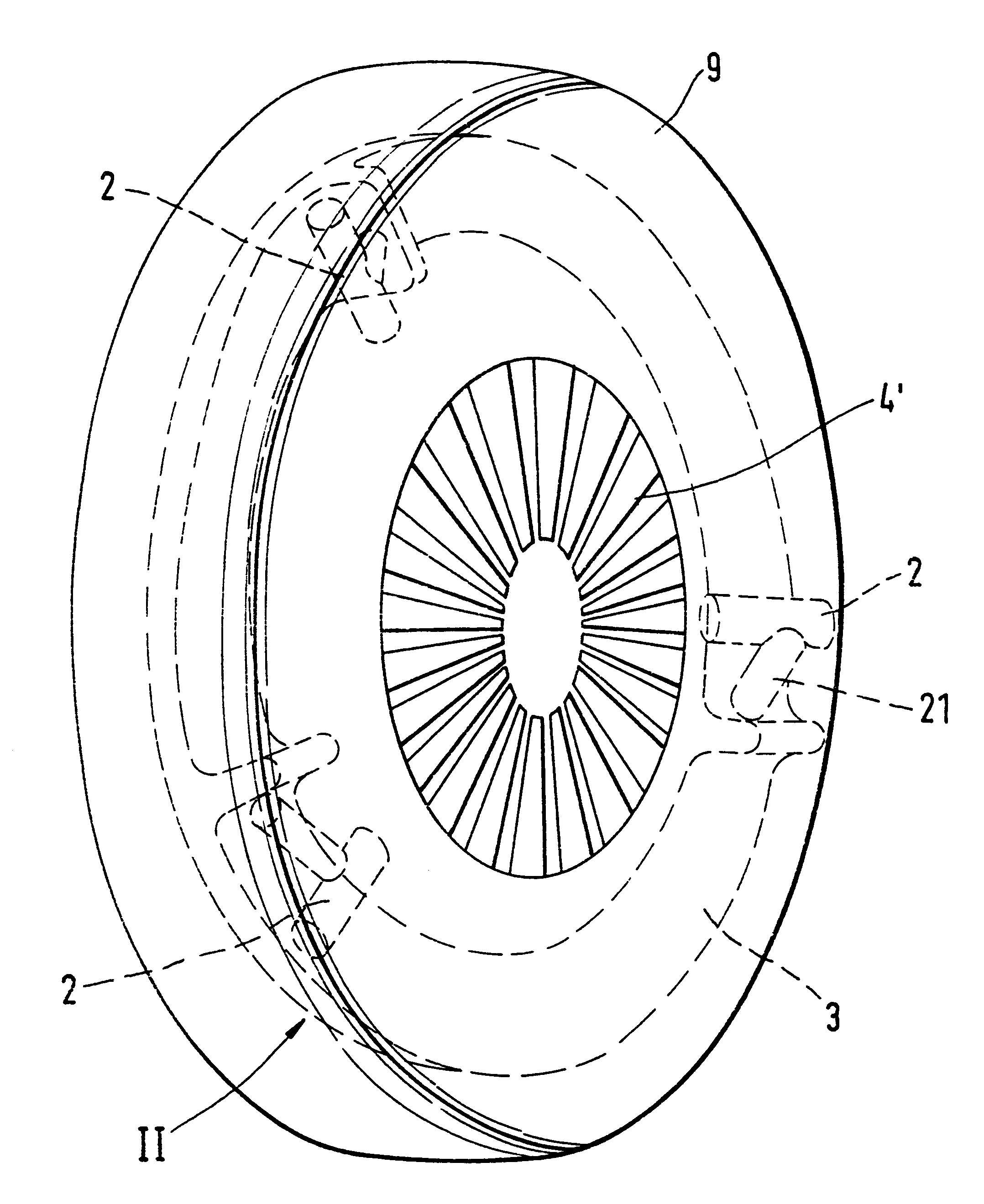
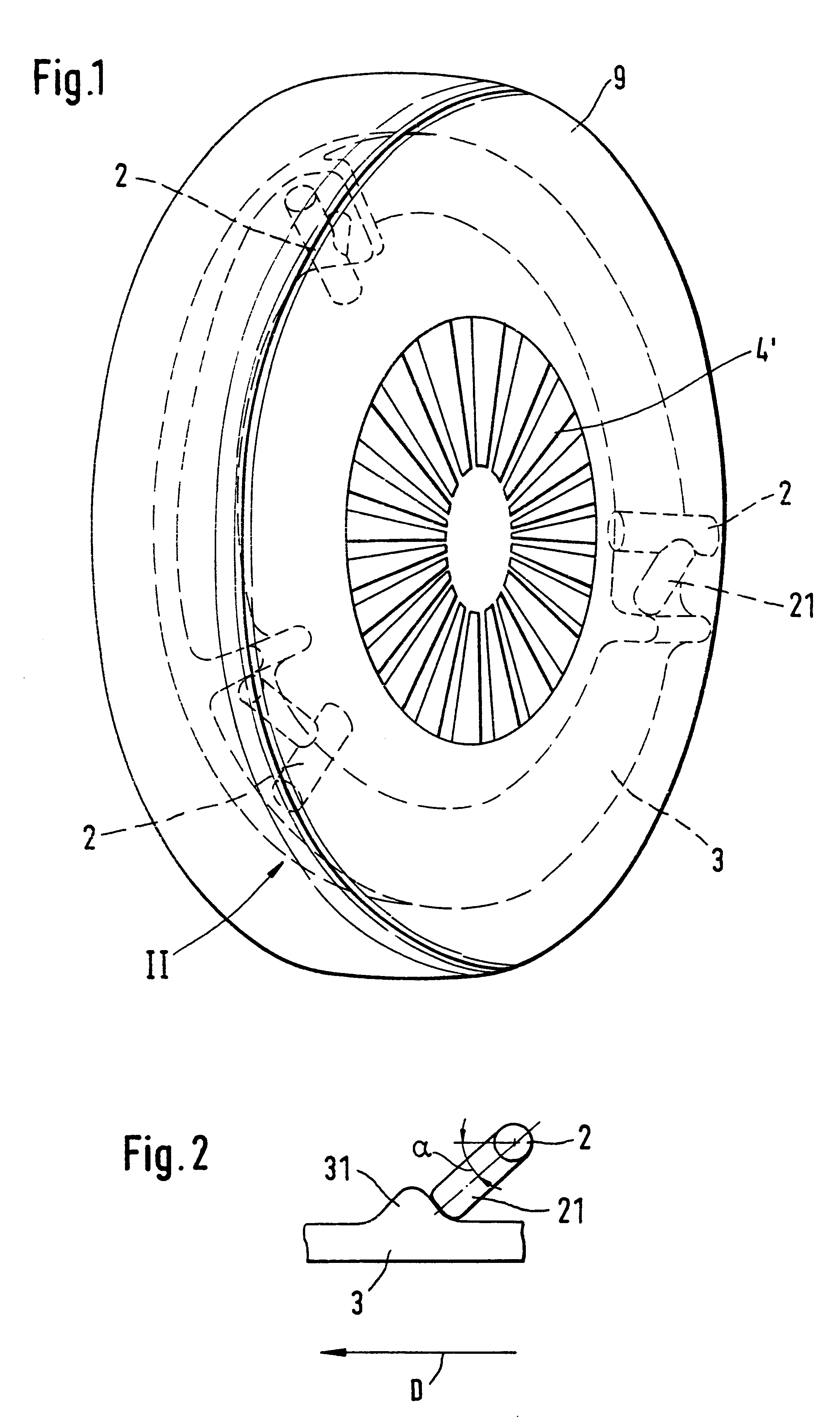
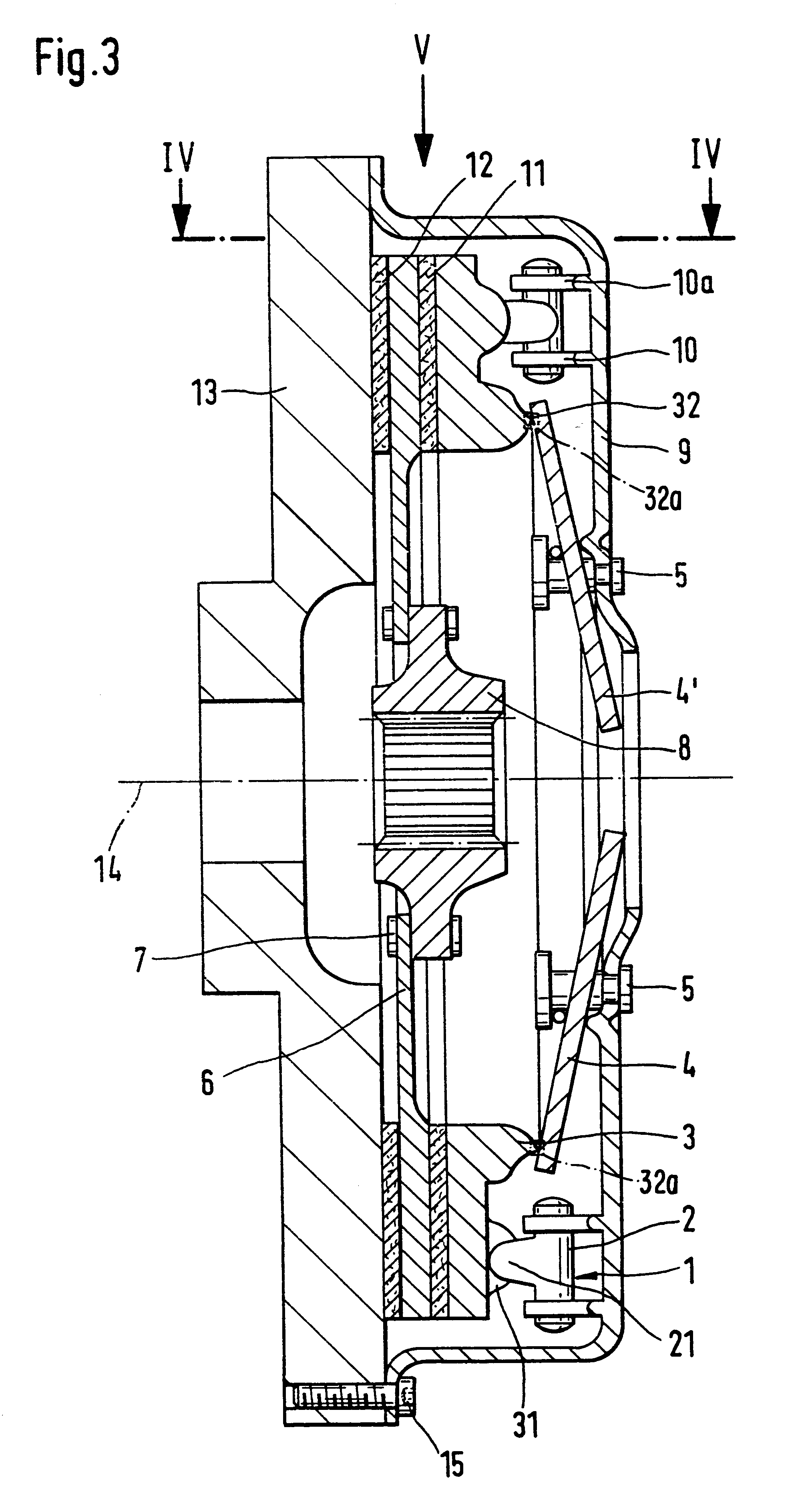
A friction clutch according to the present invention and its operation are explained with reference to FIGS. 1 to 3 and 5-6. The friction clutch comprises a clutch casing 9 connected to a flywheel 13 at a radially outer side by a screw connection 15. The flywheel 13 is attached to a crankshaft of an internal combustion engine and rotates with the crankshaft about an axis of rotation 14. A pressure plate 3 is arranged inside the clutch casing 9 and is connected to the clutch casing 9 in a rotationally fixed but axially displaceable manner. The pressure plate 3 is acted on by a pressure spring 4 which, in the present case, is a diaphragm spring. The pressure spring 4 is supported on the clutch casing 9 and exerts an engagement force on the pressure plate 3 directed toward the flywheel 13. The clamping force of the pressure spring 4 may be released via diaphragm spring tongues 4' which point radially inward. A clutch disk 6 is attached in a rotationally fixed manner to a transmission i...


PUM


Abstract

A friction clutch for motor vehicles has a casing which can be connected in a rotationally fixed manner to a driven flywheel mass. A pressure plate is arranged inside the casing with a pressure spring supported between the clutch casing and the pressure plate so that the pressure plate presses a clutch disk, which is provided with friction linings, onto the flywheel mass. The pressure spring, during engagement of the clutch, exerts a varying pressure force on the pressure plate. The friction clutch also having a device which acts on the pressure plate and varies essentially proportionally to the force of the pressure spring to force of the pressure plate.

Description

1. Field of the InventionThe invention relates to a friction clutch for motor vehicles having a clutch casing which is connectable in a rotationally fixed manner to a driven flywheel, a pressure plate arranged inside the clutch casing, and a pressure spring which is supported on the clutch casing for exerting a varying pressure force on the pressure plate during engagement of the clutch to press a clutch disk with friction linings onto the flywheel.2. Description of the Related ArtA prior art friction clutch is known, for example, from German reference DE 39 40 917 A1. This reference discloses a friction clutch having a clutch casing in which a pressure plate is rotatably fixed and axially movable. A pressure spring is actuatable for pressing the pressure plate relative to the clutch casing onto a clutch disk. An actuation device which acts on the pressure spring and is mechanically or hydraulically actuated is provided to engage and disengage the clutch. The actuation device is arr...

Claims


Application Information

Patent Timeline
IPC IPC(8): F16D13/71F16D13/58F16D13/75F16D13/64
CPCF16D13/64F16D13/71F16D13/757F16D2013/642F16D2013/706
Inventor DORFLER, MATHIASHEIARTZ, MARKUS
Owner MANNESMANN SACHS AG
Why Eureka
Try Eureka