Quasi-kinematic coupling and method for use in assembling and locating mechanical components and the like

a technology of kinematic coupling and mechanical components, which is applied in the direction of rod connection, mechanical control devices, instruments, etc., can solve the problems of pushing the performance requirements beyond the approximately ten micron repeatability limits of such techniques, not well-suited to precision assembly applications, and couplings are not ideally suited for use in high-volume manufacturing and assembly processes, and achieves low cost

Inactive Publication Date: 2001-02-27
AESOP
View PDF12 Cites 119 Cited by
  • Summary
  • Abstract
  • Description
  • Claims
  • Application Information

AI Technical Summary

Benefits of technology

An object of the present invention, accordingly, is to provide a new and improved low cost quasi-kinematic coupling and method which enable repe...

Problems solved by technology

Traditionally, precision assemblies have used precision pins and holes for part alignments; but the demands of manufacturing processes have now pushed performance requirements beyond the approximately ten micron repeatability limits of such techniques.
While certain types of prior kinematic couplings have been used to provide affordable submicron repeatability, their operation generally leaves gaps between the mated components, and they are therefore not well-suited for those types of precision assembly applications that require contact or sealing, such as in casting.
Though constituting a significant improvement, such couplings are not ideally suited for use in high volume manufacturing and assembly processes, due to the cost of manufacturing and assembling the flexural and kinematic components.
Another limitation of these couplings resides in their inability to be arranged so that most of the resistance to error-causing loads is aligned in a common direction, while maintaining high stiffness in an orthogonal direction.
Accomplishing this function in prior classical or flexural kinematic couplings is...

Method used


Image

  • Quasi-kinematic coupling and method for use in assembling and locating mechanical components and the like
  • Quasi-kinematic coupling and method for use in assembling and locating mechanical components and the like
  • Quasi-kinematic coupling and method for use in assembling and locating mechanical components and the like

Examples


Embodiment Construction

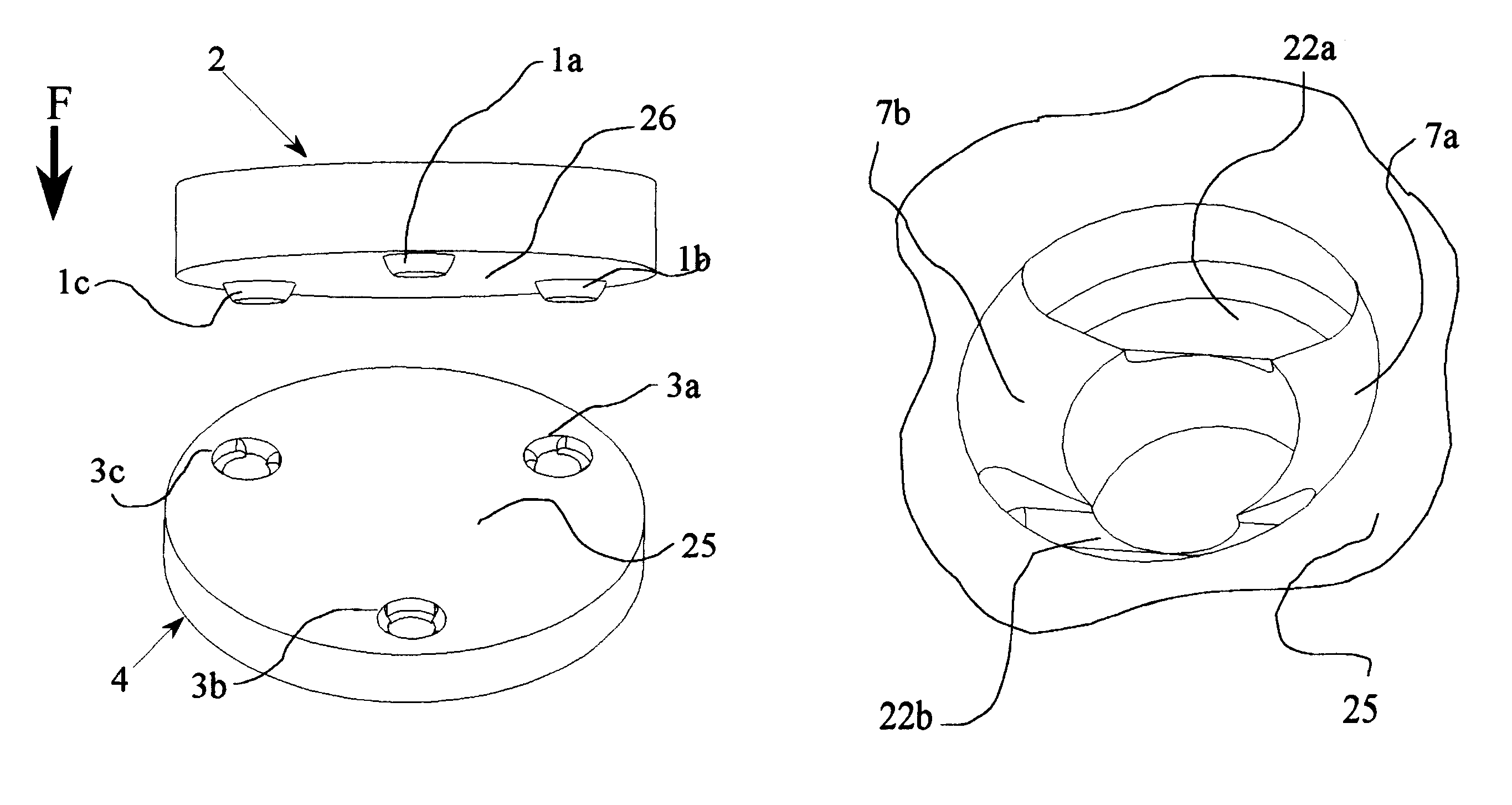
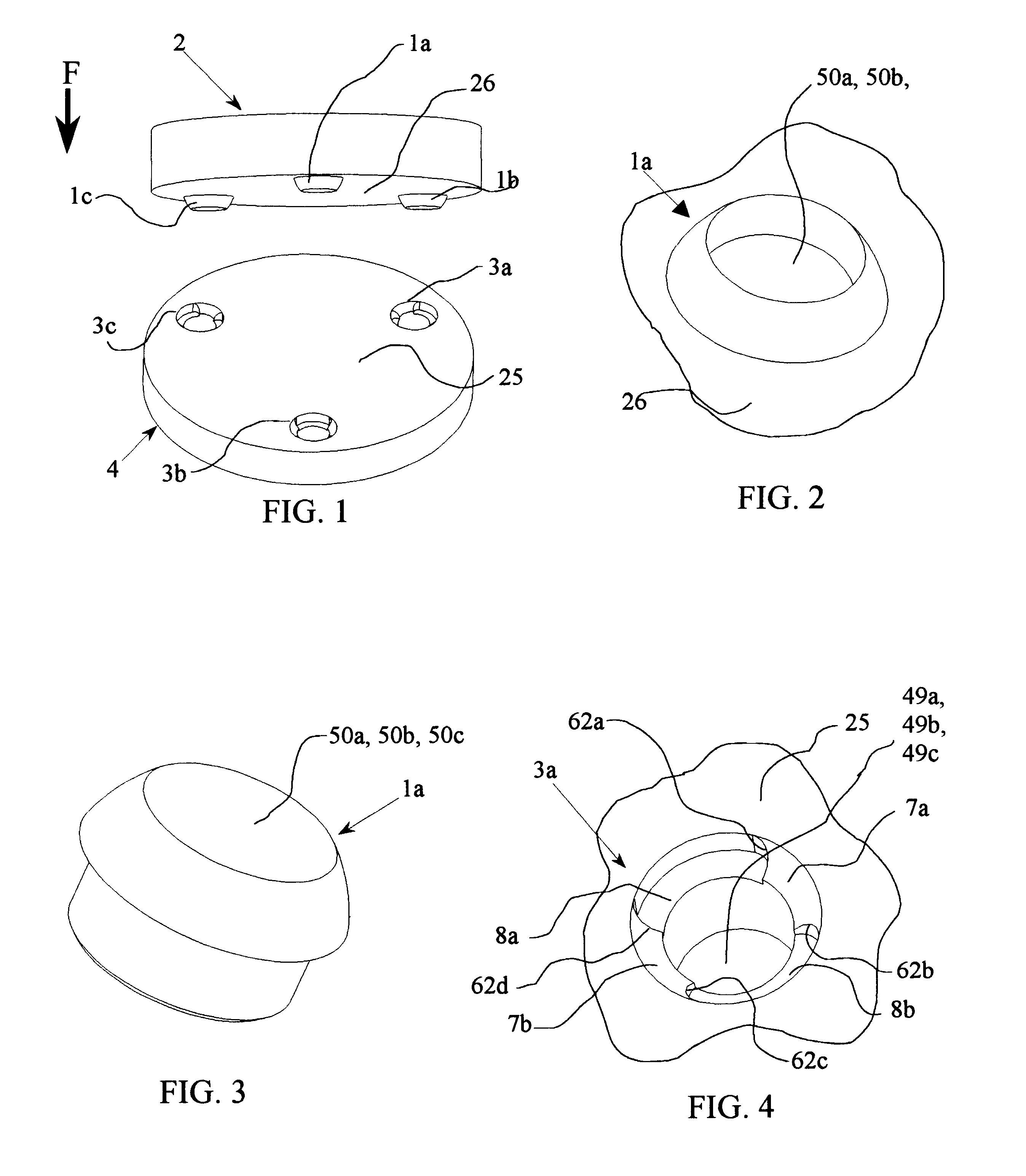
FIG. 1 shows the open coupling 2-4 of the invention in its generic form. The coupling consists of three spaced conical grooves 3a, 3b, and 3c attached to or machined into the inner surface 25 of the first (lower) component 4, and three corresponding spherical peg or protruding elements 1a, 1b, and 1c attached or machined into the opposing or inner surface 26 of the second (upper) component 2, FIGS. 1 and 2. When such a coupling is initially mated, each spherical protrusion element 1a, 1b, and 1c contacts its corresponding conical groove 3a, 3b, and 3c, and surfaces 25 and 26 will be parallel and separated by a small gap.

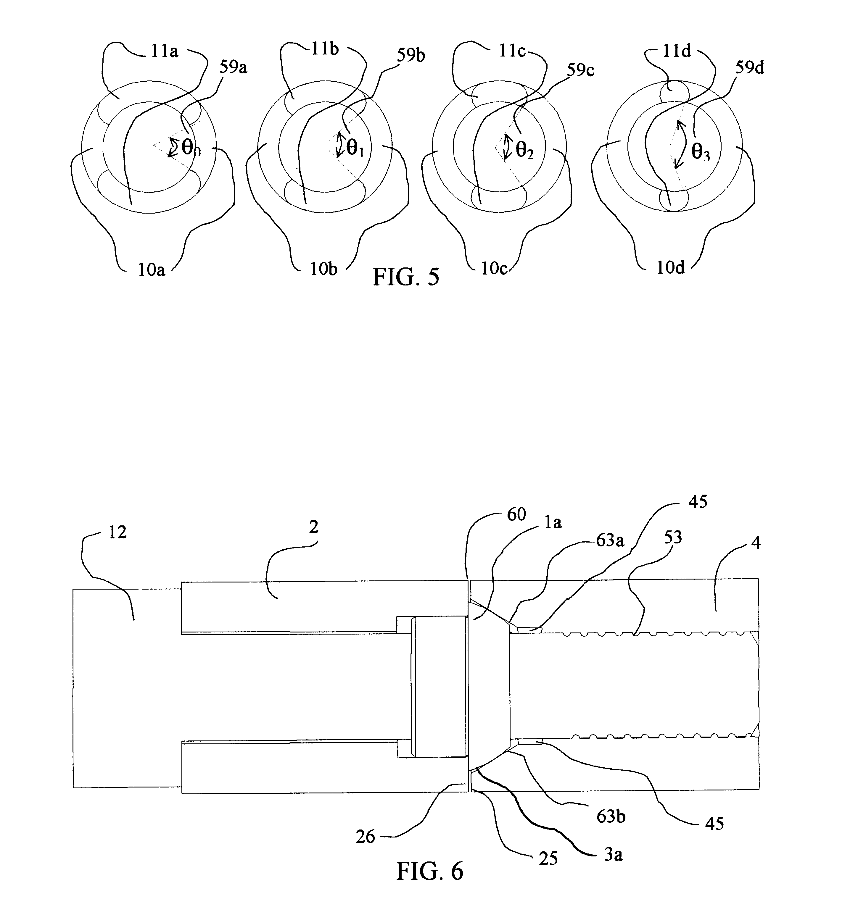
This contact takes place on seats of the conical grooves, as shown at 7a and 7b for the illustrative groove 3a, in FIG. 4 and FIG. 7. The contact can be modeled as along lines 17a and 17b, FIG. 7, since the surfaces of the spherical elements 1a, 1b, and 1c and the surfaces of the conical grooves 3a, 3b, and 3c are surfaces of revolution. With each conical groove 3a, ...


PUM


Abstract

A quasi-kinematic coupling for mating components (mechanical parts, surfaces, assemblies and the like) employing mating sets of surface of revolution, (conical) grooves and cooperative surface of revolution (spherical/conical) protrusions for establishing six lines (not just prior points) of contact at the kinematic interfaces, and with elastic compliance therebetween and preferably with relief features to define the effective orientation as a clamping force seats the protrusions in the grooves and seals the component mating surfaces into contact.

Description

The present invention relates to the coupling of mechanical component parts, surfaces or assemblies and the like (hereinafter sometimes generically termed "components"), where low cost and repeatable coupling are desired, as, for example, in applications and processes involving machine tool fixtures and other general assembly applications.Better precision at lower cost is a major driving force in design and manufacturing. Traditionally, precision assemblies have used precision pins and holes for part alignments; but the demands of manufacturing processes have now pushed performance requirements beyond the approximately ten micron repeatability limits of such techniques. Next generation assemblies, such as, for example, machining fixtures, require low cost methods of assembly with consistently better than ten microns repeatability. The present invention is accordingly directed to a fundamentally new kinematic coupling, termed here a "quasi-kinematic" coupling, which meets the more st...

Claims


Application Information

Patent Timeline
IPC IPC(8): B23P19/00
CPCB23P19/10Y10T403/7039Y10T403/1624Y10T403/1616Y10T403/635Y10T403/16F16B2200/10
Inventor CULPEPPER, MARTINSLOCUM, ALEXANDER H.
Owner AESOP
Why Eureka
Try Eureka