Targeting of flying insects with insecticides and apparatus for charging liquids

a technology for insecticides and flying insects, applied in the direction of insect catchers and killers, liquid dispensing, combustion processes, etc., can solve the problems of high probability of contact between insects and droplets, and push droplets away, and achieve the effect of reducing the flow rate of liquid

Inactive Publication Date: 2001-03-13
UNIV OF SOUTHAMPTON +1
View PDF9 Cites 85 Cited by
  • Summary
  • Abstract
  • Description
  • Claims
  • Application Information

AI Technical Summary

Benefits of technology

This improvement in the interaction between the charged droplets and the insects will be due to the combined effect of the additional diffusion forces generated within the charged cloud of droplets by the electrical field leading to modification of the trajectory of each droplet so that each droplet is directed to an insect. The insecticide is attracted to the whole surface of each insect. This improves the targeting of the insecticidal droplets onto the insects.
The improved targeting of droplets of an insecticidal composition onto flying insects is likely to offer two important advantages over conventional systems. First, the knock-down rate is likely to be improved since more insecticide actually alights on each insect in a given time period. Secondly, current knock-down rates may be maintained with a lower level of active ingredient in the insecticide product.

Problems solved by technology

Due to the high density of insecticide droplets in the plume produced during spraying, there is a high probability that contact will occur between the insects and the droplets.
However, when insects are in flight the air disturbances around their bodies caused by the beating of wings may actually push droplets away.

Method used


Image

  • Targeting of flying insects with insecticides and apparatus for charging liquids
  • Targeting of flying insects with insecticides and apparatus for charging liquids
  • Targeting of flying insects with insecticides and apparatus for charging liquids

Examples


example 1

A fluorometric assay was designed. Calliphora erythrocephala flies were freshly killed by freezing for one hour. They were then removed from the freezer and left for two hours to reach room temperature again. Each fly was weighed and then individually pinned to a nylon rod by a fine entomological pin (E3) passing through the side of the thorax. A standard aerosol spray can of Mortein Ultra Low Allergenic insecticide (Reckitt & Colman, Australia), with 0.5% "Fluorescein" (Acid Yellow 73, Aldrich) added to the formulation, was weighed, well shaken and placed at a distance of 1.8 meters from the fly in an electrically isolated plastic holder. The can was aligned so that the fly was centrally placed in the stream of droplets of the product that could be sprayed from the aerosol spray can.

A two second spray of droplets of the product was emitted onto the fly. The fly was immediately removed from the pin and placed in a vial containing 5 ml of cold phosphate buffer solution (pH 6.8, 0.1 M...

example 2

Enhanced Knockdown of Musca domestica

Knock-down experiments were done in a British standard size fly room measuring 400 cm long by 290 cm wide by 250 cm high. The room was evenly lit with fluorescent lights, and maintained at a temperature of 22.0.+-.3.0.degree. C. 25 male and 25 female Musca domestica flies of between 3 and 7 days post emergence were used for all of the tests. An aerosol spray can of domestic insecticide was placed in an electrically isolated plastic holder with a brass screw contacting an area of the can from which the paint had been removed. The insecticide product was sprayed for 1.+-.0.1 second by depressing a lever of the can holder.

After a period of 1 second the flies were released into the plume of insecticide at a distance of 180 cm from the can. The number of flies incapable of co-ordinated movement were counted at 0.5, 1.5, 2.0, 2.5, 3.0, 4.0, 6.0, 8.0 and 12.0 minutes after the spray of insecticide. A minimum of 5 replicates were performed for each varia...

example 3

An insecticidal composition was prepared from the following components:

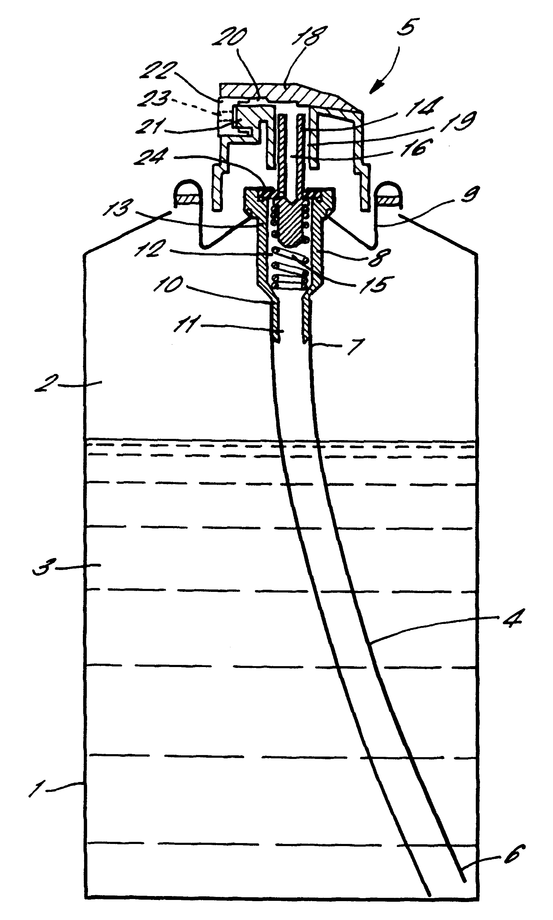
The composition was introduced into tinplate aerosol cans having valve assemblies comprising a 3.00 mm polypropylene diptube, 1.27 mm housing orifice, 0.64 mm vapour phase tap and 2.times.0.61 mm stem holes. Two sprays were compared, one with a single-piece actuator with a 0.85 mm diameter circular orifice and one with a two piece button-style actuator with an insert as shown in FIG. 7.1 of the accompanying drawings. The spray characteristics achieved with the two actuators were very similar. The charge-to-mass ratio of the insecticidal formulation achieved with the 0.85 mm circular orifice was -2.52.times.10.sup.-5 C / kg, and with the orifice in FIG. 7.1 the charge-to-mass ratio was -1.06.times.10.sup.-4 C / kg.

Knockdown and mortality of house flies, Musca domestica, was compared for the two insecticide variables, according to the CERIT (Centre for Entomological Research and Insecticide Technology) space spray prot...


PUM


Abstract

A method of killing flying insects which method comprises spraying into the air in which insects are flying liquid droplets of an insecticidal composition, a unipolar charge being imparted to the said liquid droplets by double layer charging and charge separation during spraying, the unipolar charge being at a level such that the said droplets have a charge to mass ratio of at least + / -1x10⁻⁴ C / kg. An aerosol spray device which is capable of imparting a unipolar charge by double layer charging and charge separation to liquid droplets of a composition sprayed therefrom has a spraying head in the form of an insert in an actuator, the spraying head having a bore through which liquid is expelled having an outlet, preferably with a tortuous periphery, having an L / a ratio of at least 8 (preferably at least 10) where L is the length of the periphery defining the bore outlet in mm and a is the cross-sectional area of the bore outlet in mm2 and the apparatus being constructed such that the droplets are expelled from the spraying head at a flow ratio of at least 0.4 (preferably at least 0.5) grams per second and have a charge to mass ratio of at least + / -1x10⁻⁴ C / kg.

Description

The present invention relates to a method and apparatus for killing flying insects by spraying insecticide into the air in which the insects are flying, and in particular to methods of improving the targeting of the insects with the insecticide.The efficiency of insecticide sprays in killing flying insects depends, in part, upon how much of the insecticide contacts the insects which are to be killed. Current methods of applying the insecticide rely on the mechanical interaction between the sprayed droplets of insecticide and each flying insect. Aerosol insecticide sprays may be dispersed into areas through which insects may fly and thus encounter the droplets of insecticide, or aerosol insecticide sprays may be aimed at specific target insects. Due to the high density of insecticide droplets in the plume produced during spraying, there is a high probability that contact will occur between the insects and the droplets. However, when insects are in flight the air disturbances around t...

Claims


Application Information

Patent Timeline
Patent Type & Authority Patents(United States)
IPC IPC(8): B05B5/025B05B5/00B05B5/16B05B5/047B05B1/34B65D83/14A01M7/00B05B9/04B65D83/34B65D83/36
CPCB05B1/3436B05B5/047B05B5/1691B65D83/303B65D83/75B65D83/753
Inventor FOX, RODNEY THOMASHARRISON, NEALE MARKHUGHES, JOHN FARRELLWHITMORE, LINDSEY FAYE
Owner UNIV OF SOUTHAMPTON
Why Eureka
Try Eureka