Optical filtering device

a filtering device and optical filter technology, applied in the direction of optical radiation measurement, instruments, spectrometry/spectrophotometry/monochromators, etc., can solve the problems of high intensity radiation source dazzle, no improvement in imaging performance,

Inactive Publication Date: 2001-03-20
THE SEC OF STATE FOR DEFENCE IN HER BRITANNIC MAJESTYS GOVERNMENT OF THE UK OF GREAT BRITAIN & NORTHERN IRELAND
View PDF11 Cites 33 Cited by
  • Summary
  • Abstract
  • Description
  • Claims
  • Application Information

AI Technical Summary

Problems solved by technology

Dazzle produced by high intensity radiation sources is a common problem in optical systems such as imaging devices.
However, such an arrangement provides no improvement in imaging performance in the presence of a dazzling source.

Method used


Image

  • Optical filtering device
  • Optical filtering device
  • Optical filtering device

Examples


Embodiment Construction

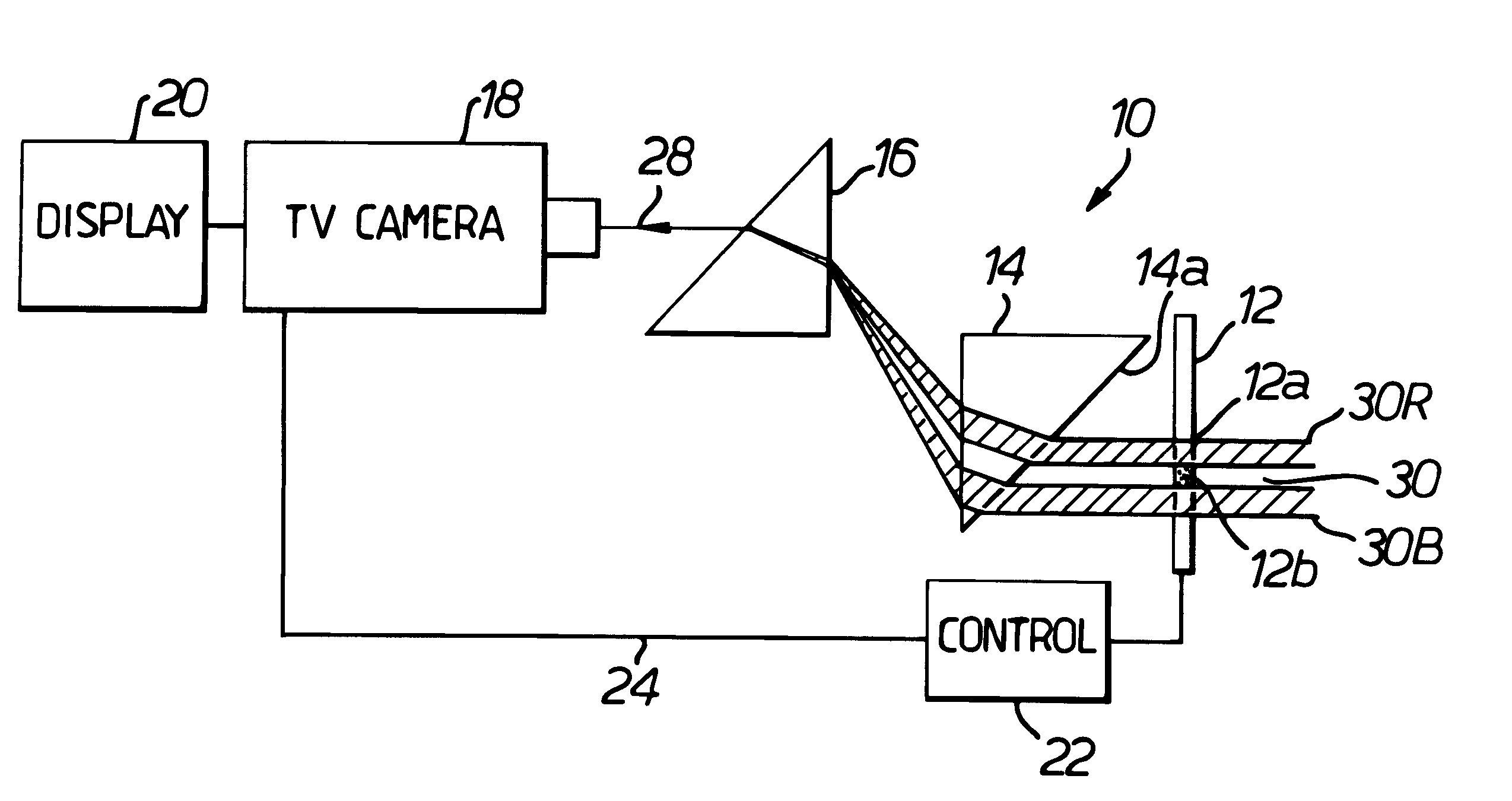
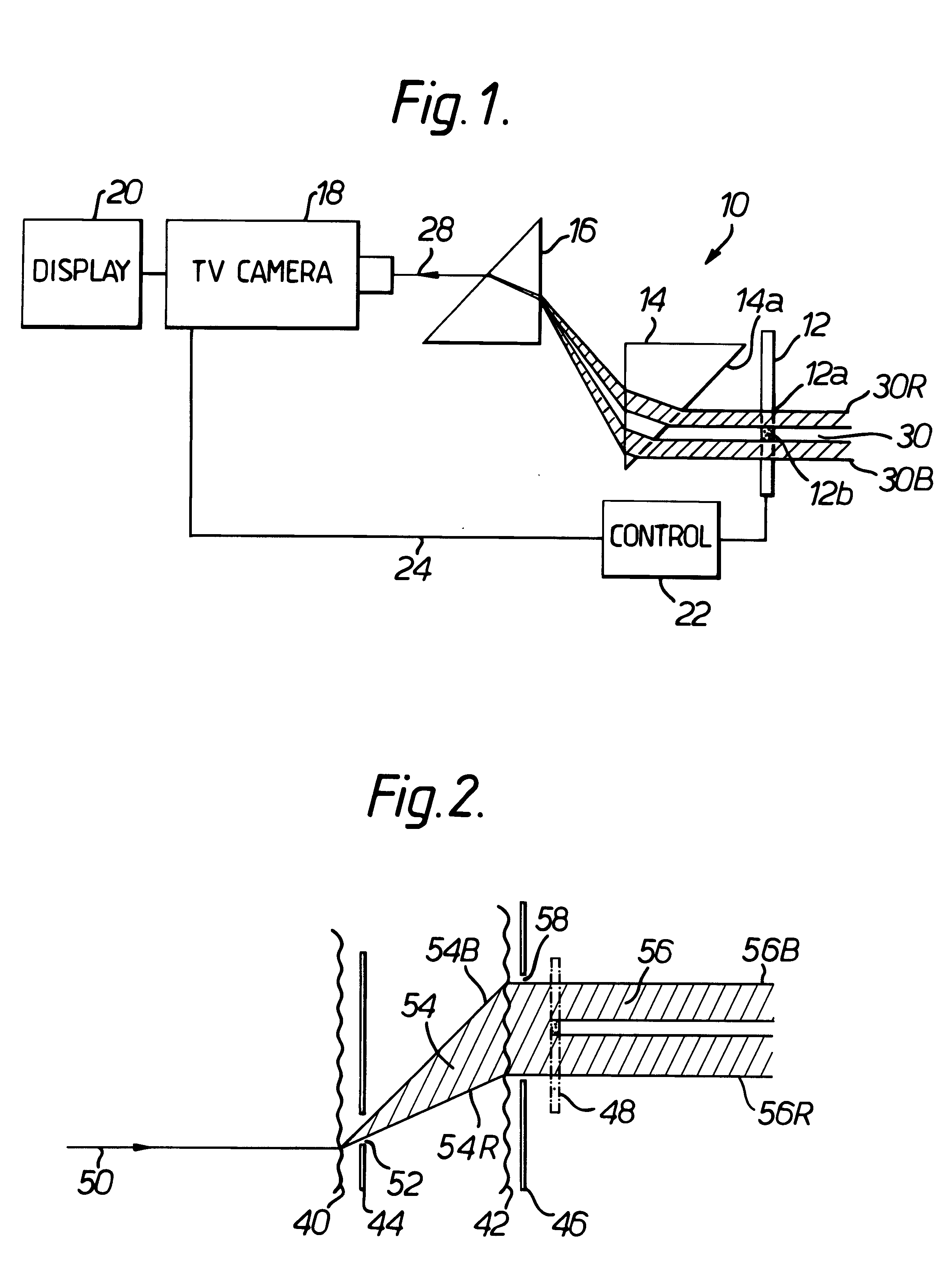
Referring to FIG. 1, there is shown a schematic drawing of an optical filtering device of the invention indicated generally by 10. The device 10 incorporates an optical stop 12, first and second prisms 14 and 16, a closed circuit television camera 18 and associated display 20, together with a control unit 22 connected in a feedback loop 24 between the camera 18 and the optical stop 12. The prisms 14 and 16 are of like size, shape, composition and dispersion, and are disposed so that their angular dispersions are mutually parallel but opposite. They are right isosceles triangular in section. The camera 18 incorporates an objective lens (not shown) with a 100 mm focal length. This lens is arranged to receive light indicated by a central white light ray 28 from a remote scene region (not shown) via the prisms 14 and 16.

The optical stop 12 is a liquid crystal spatial light modulator having transparent pixels exemplified by a single pixel 12a and opaque pixels exemplified by a single pix...


PUM


Abstract

An optical filtering device incorporates first and second prisms, the latter prism counteracting the angular dispersion of the former prism. A spatial light modulator provides a positionally variable optical stop located to block radiation within a wavelength interval and received from a location within a scene. Unobscured radiation from that and other scene locations passes to a camera, which produces an image on a display. Opaque pixels in the stop are positioned to block unwanted light sources. The invention attenuates potentially dazzling monochromatic radiation while retaining radiation at other wavelengths for imaging purposes.

Description

1. Field of the InventionThis invention relates to an optical filtering device. More particularly, although not exclusively, it relates to a device suitable for selectively reducing the intensity of unwanted radiation in an optical system, such as that arising from a high intensity monochromatic localised source.2. Discussion of Prior ArtDazzle produced by high intensity radiation sources is a common problem in optical systems such as imaging devices. United Kingdom Patent No. 1,115,864 describes a gas cell used to protect a radiation detector against damage from high intensity radiation. The pressure of gas in the cell is such that, at sufficiently high radiation intensity, the gas breaks down into a plasma which scatters and attenuates unwanted radiation. However, such an arrangement provides no improvement in imaging performance in the presence of a dazzling source. It merely provides protection against damage. There is for example a need for a device capable of selectively block...

Claims


Application Information

Patent Timeline
Patent Type & Authority Patents(United States)
IPC IPC(8): G01J3/02G01J3/12G01J3/16G01J3/00G02B5/20G02B26/00
CPCG01J3/02G01J3/0229G01J3/16G02B5/20G02B5/203G02B26/00
Inventor BEALE, MARC I JLEWIS, MEIRION F
Owner THE SEC OF STATE FOR DEFENCE IN HER BRITANNIC MAJESTYS GOVERNMENT OF THE UK OF GREAT BRITAIN & NORTHERN IRELAND
Why Eureka
Try Eureka