
Laminated composite building component

a technology of laminated polymeric foam and building components, which is applied in the direction of girders, transportation items, transportation and packaging, etc., can solve the problems of lateral force resistance and other problems, and achieve the effect of maximizing the total encapsulation, great strength, and strong capability

Inactive Publication Date: 2001-03-27
RYN SUTELAN
View PDF20 Cites 122 Cited by
  • Summary
  • Abstract
  • Description
  • Claims
  • Application Information

AI Technical Summary

Benefits of technology

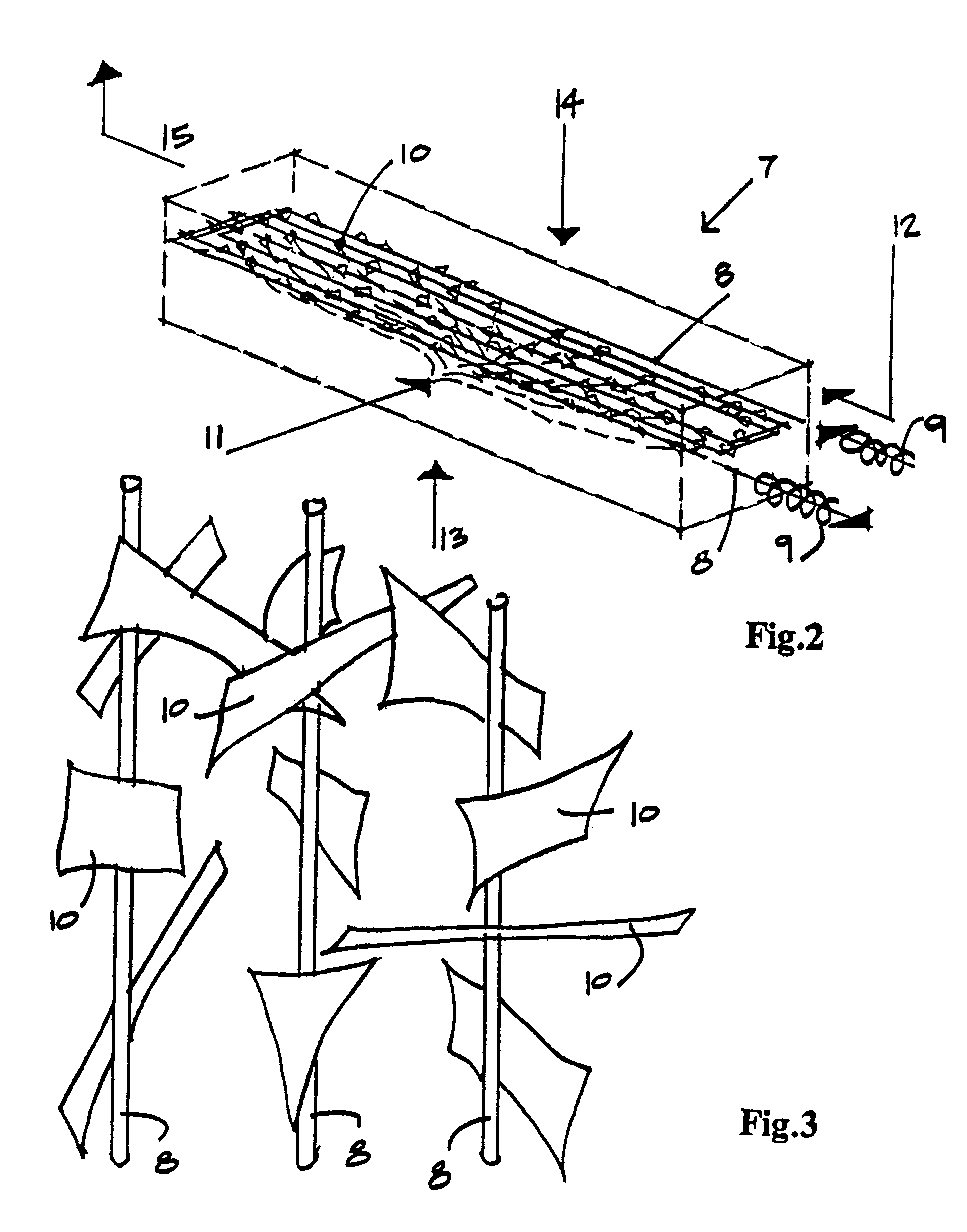
In the present invention with the exception of the stressed-skin sheets, the primary supporting structure is inside the body of the core with the laminate contact area maximized by total encapsulation. In known materials, the beneficial laminate effect of plastic foam on a relatively flimsy planar structure has demonstrated a great strength which the present invention intends to amplify. After encapsulation, the next priority is a versatile geometry that lends itself to both universal distribution and continuous spool feed into the cavity of the mold. Pursuant to this method, elongated circular and flat shapes such as wire and ribbon are favored, wire more versatile but ribbon stronger in one direction. As a structural prototype, consider a Styrofoam.TM. cylinder about the size of a wooden spool of thread. Next, push straight pins into the end of the cylinder. Depending upon the ultimate composite strength desired, one could put any number from one to one-hundred pins into the shape and, depending on the quantity selected, obtain a scientifically and mathematically predictable change in the structural performance of the Styrofoam.TM. cylinder. Finally, primecoat the pins with an adhesive which bonds them to the cellular structure of the Styrofoam.TM. for additional composite strength.
FIG. 37 is a simple house assembly, showing the application of prefabricated composite panels of the present invention throughout.

Problems solved by technology

Below is overdesign, and above is unacceptable, but conducive to homogeneity.
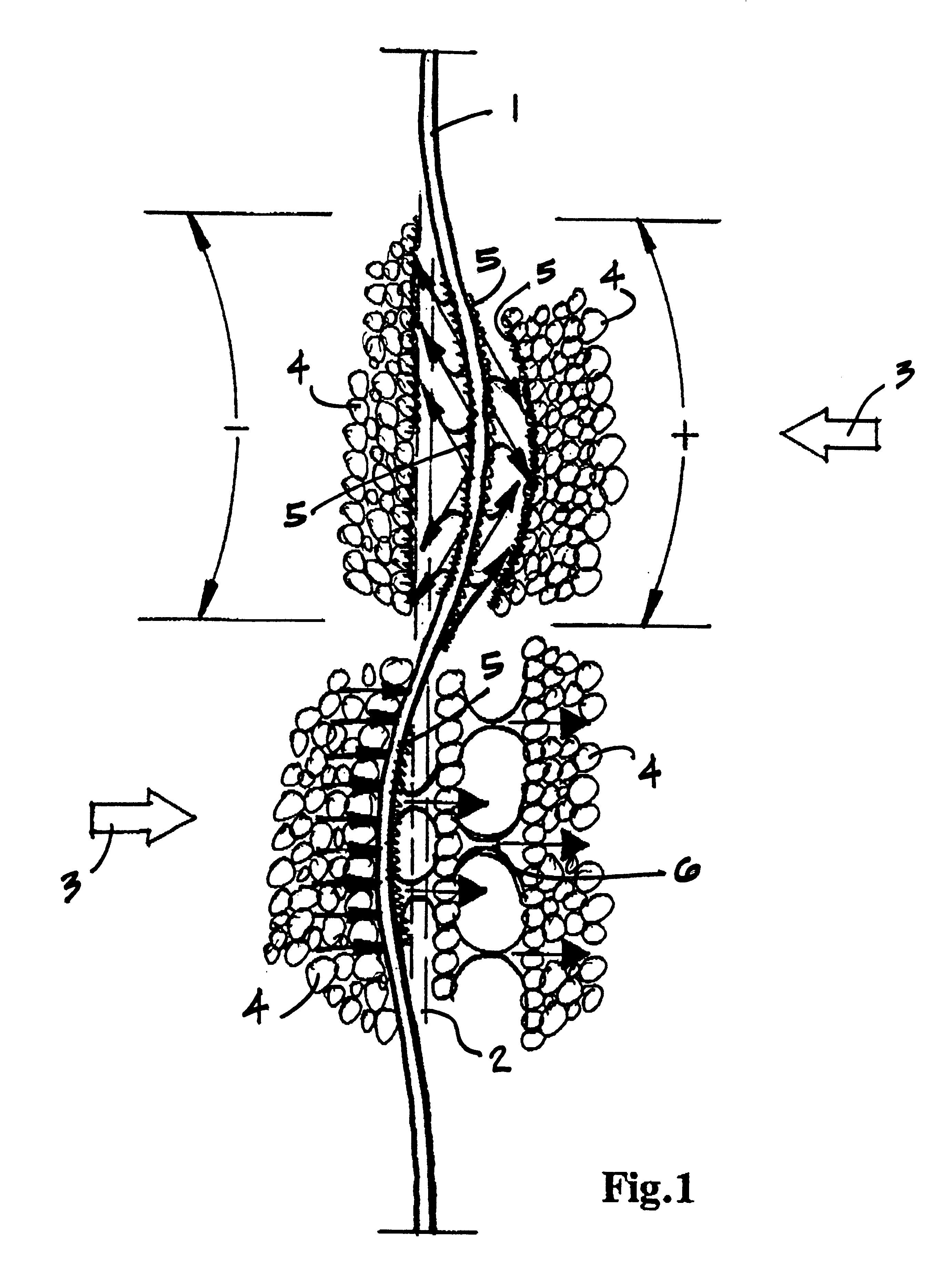
In essence, the laminate effect of skeleton and core tends to reduce the effective unbraced member length to zero, thus lowering the "slenderness ratio" also to almost nothing, thereby resulting in a tremendous resistance to lateral force and, ultimately, to failure.

Method used


Image

  • Laminated composite building component
  • Laminated composite building component
  • Laminated composite building component

Examples


Embodiment Construction

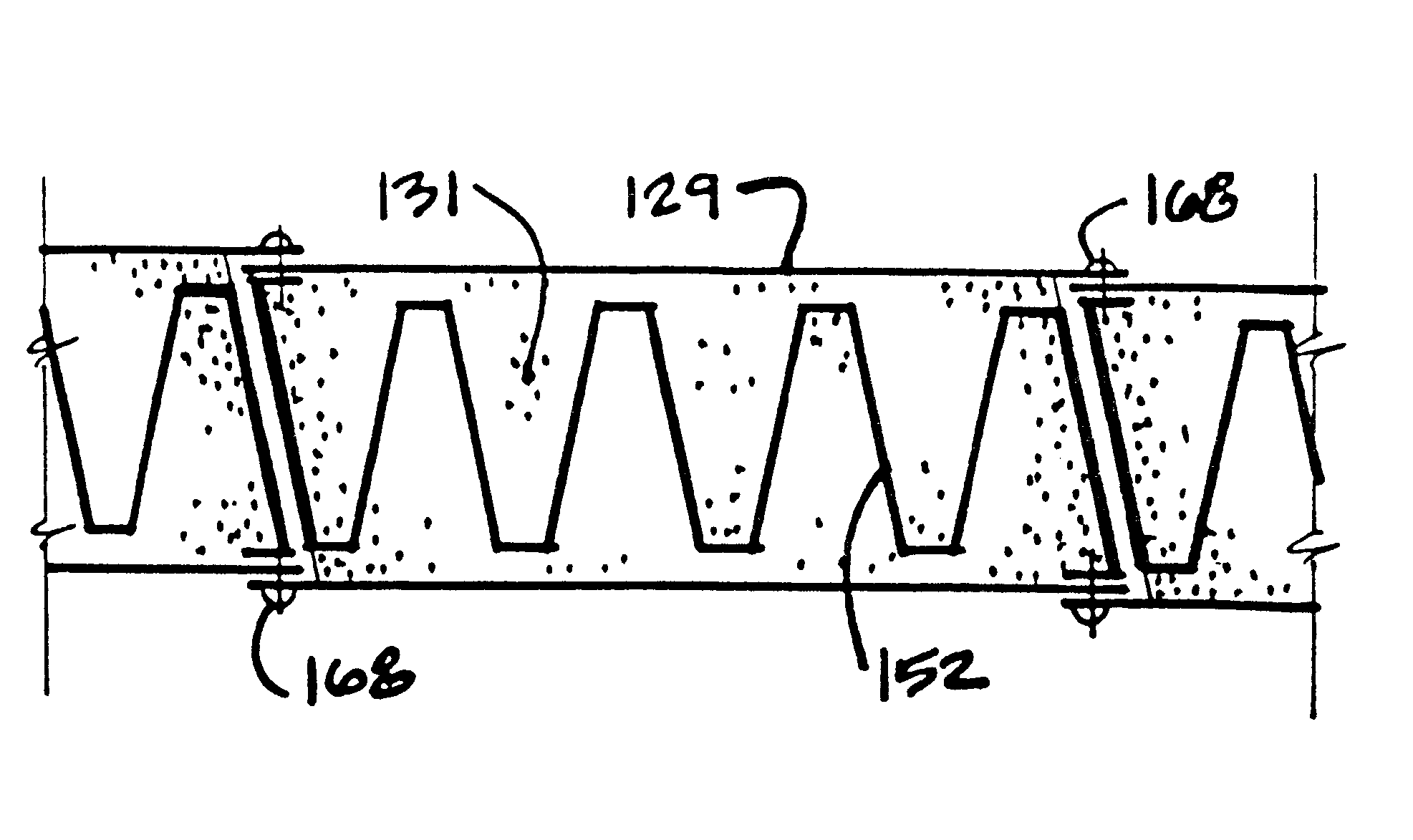
The scope of the present invention is to create a fire resistant and homogeneous laminated composite building material, comprising the lamination of rigid and resilient materials under conditions of heat, pressure and the constriction of a mold, that generates a synthetic homogeneity for reliable structural analysis. The rigid material, as the primary high performance structure capable of sustained stress, is either laminated to the surface of the composite as a stressed-skin membrane, or encapsulated within the body of the core as a corrugated sheet or skeleton structure that is bonded to and laterally braced by the resilient material. As a surface laminate, the membrane may also be fire resistant. As a corrugated sheet, it may also be thermoformed and integrated into the body of the composite in a continuous manufacturing process. And, as a skeleton, its structure may be a plurality of high strength elongate members arranged in parallel according to anticipated axial stresses. The...


PUM

PropertyMeasurementUnit
Temperatureaaaaaaaaaa
Pressureaaaaaaaaaa
Dimensional stabilityaaaaaaaaaa

Abstract

A laminated composite building component, capable of sustained axial stress as a primary support structure and enclosure of a building structure, comprising a lamination of rigid and resilient material, said rigid material formed of sheets with continuous corrugations parallel to the supporting axis and which have opposite faces being bonded to and encapsulated by said resilient material, said resilient material being a cellular foam matrix, an adhesive or fusion that bonds the rigid and resilient material together in either a static or continuous laminating process, said resilient material forming two outer surfaces spaced from the rigid material, said rigid material having opposite lateral edges being exposed from said resilient material, said lateral edges of the rigid material having return flanges for interlocking said laminated composite building component with adjacent building component, and said building components capable of being supplied and distributed in generic lengths and custom field-cut like lumber.

Description

A laminated composite building component, capable of sustained axial stress as a primary support and enclosure of a building, wherein corrugated sheets with lateral edges configured to interlock with adjacent components are encapsulated and stiffened by a foam matrix.Historically, the effective strength of a column never approaches the ultimate strength of the material it's made of, because failure always precedes it due to inherent weaknesses in its shape. A column is a structural unit carrying loads which act parallel to the longitudinal axis of the member. If the applied load is eccentric to the axis, there is a lateral deflection and a resultant bending stress which combine with the direct compression and ultimately lead to failure of the member due to buckling. If the load could be applied exactly coincident with the longitudinal axis . . . if the member were perfectly straight . . . and if the material were homogeneous . . . then the column would be stressed in pure compressio...

Claims


Application Information

Patent Timeline
IPC IPC(8): B29C44/12B29C44/02B29C70/08B32B3/28B60P3/14E04C2/26E04C3/29E04C2/34E04B1/14E04B1/02E04C2/36E04B7/10E04C2/296E04B2/84
CPCB29C44/12B29C70/086B32B3/28B60P3/14E04B1/14E04C2/296E04C2/3405E04C2/365E04C3/291E04B7/102E04B2/845Y10T428/24694E04C2002/3444Y10T428/233Y10T428/24996B32B5/024B32B2331/04B32B2315/085
Inventor SUTELAN, FRANK
Owner RYN SUTELAN
Learn More