

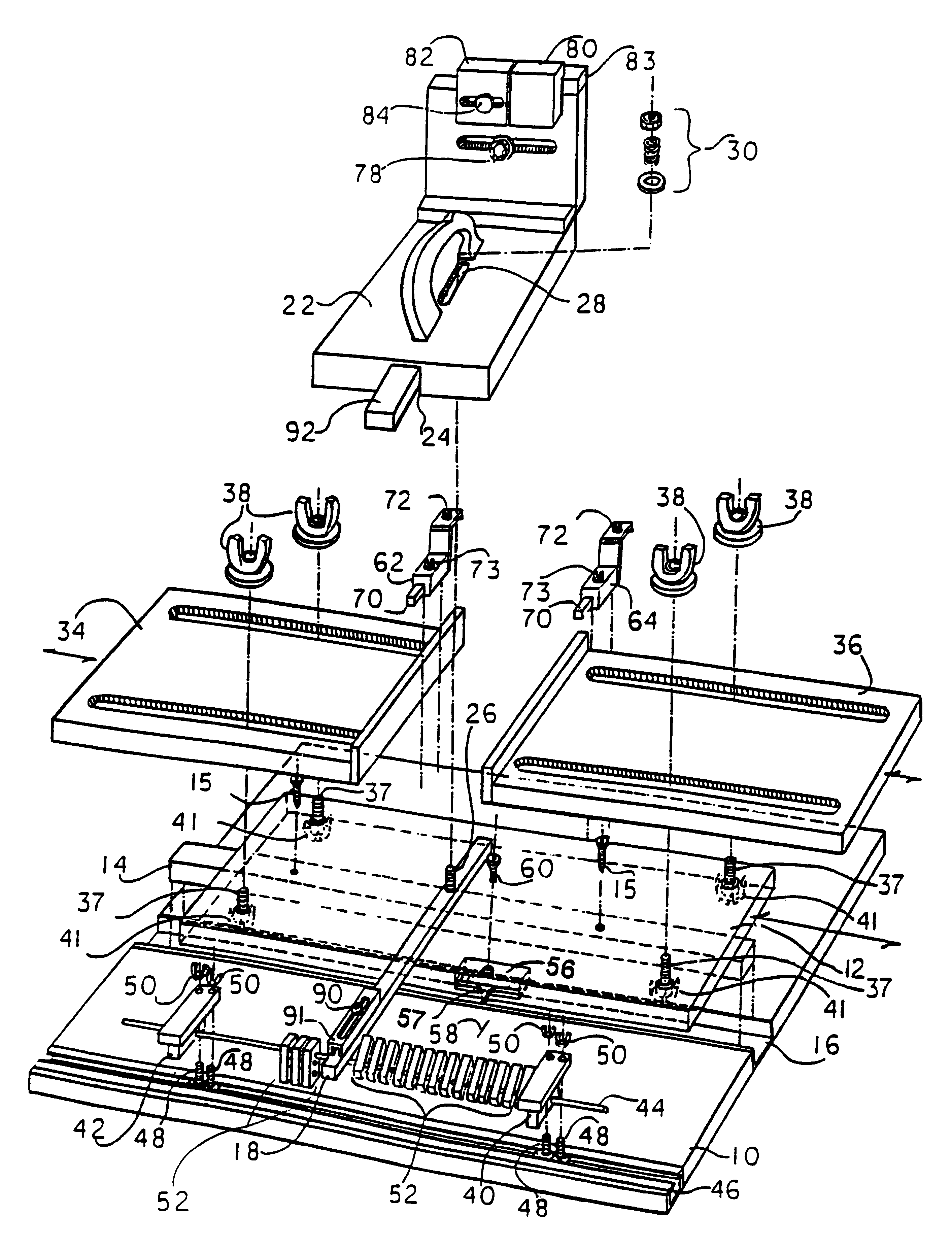
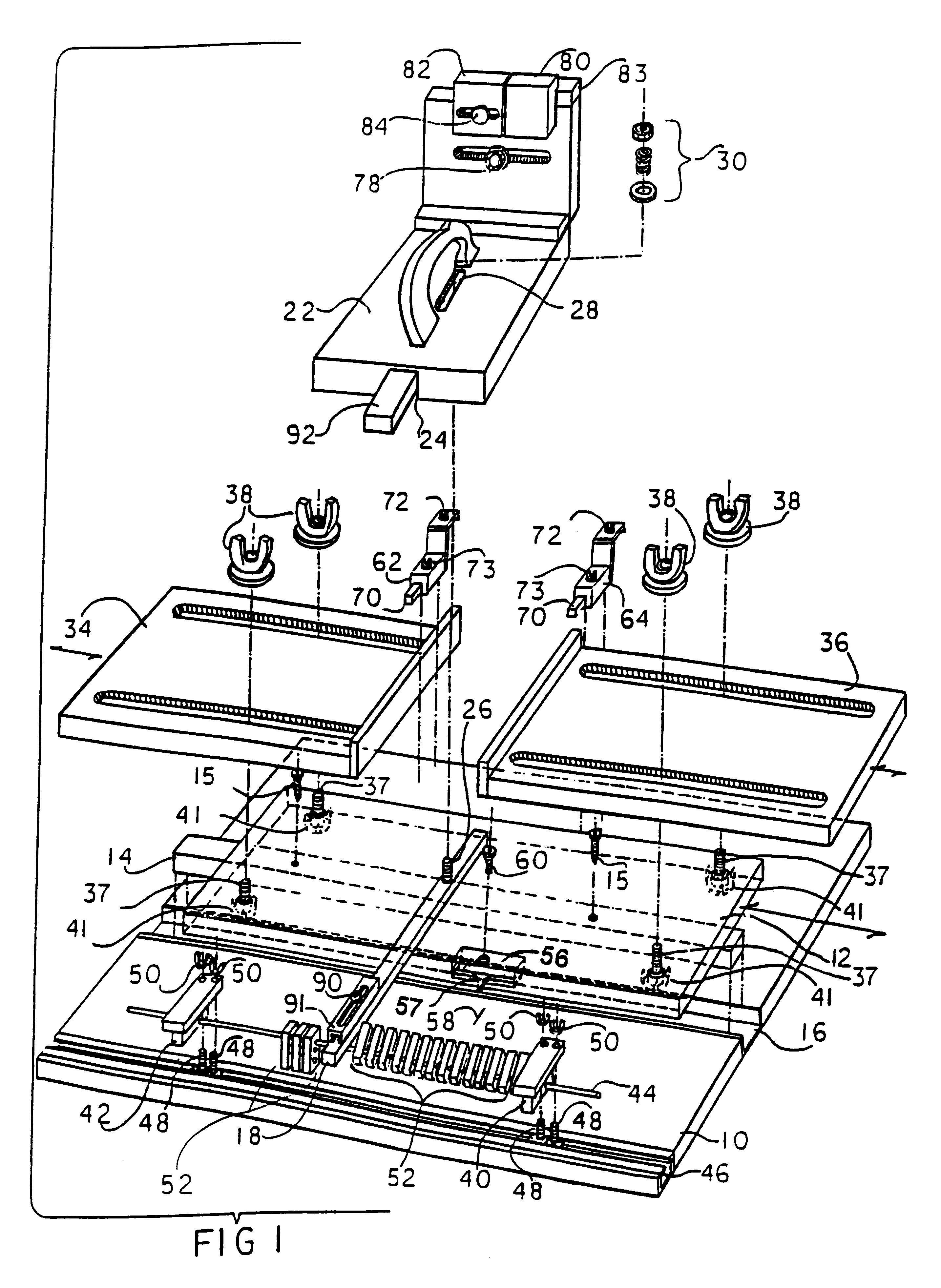
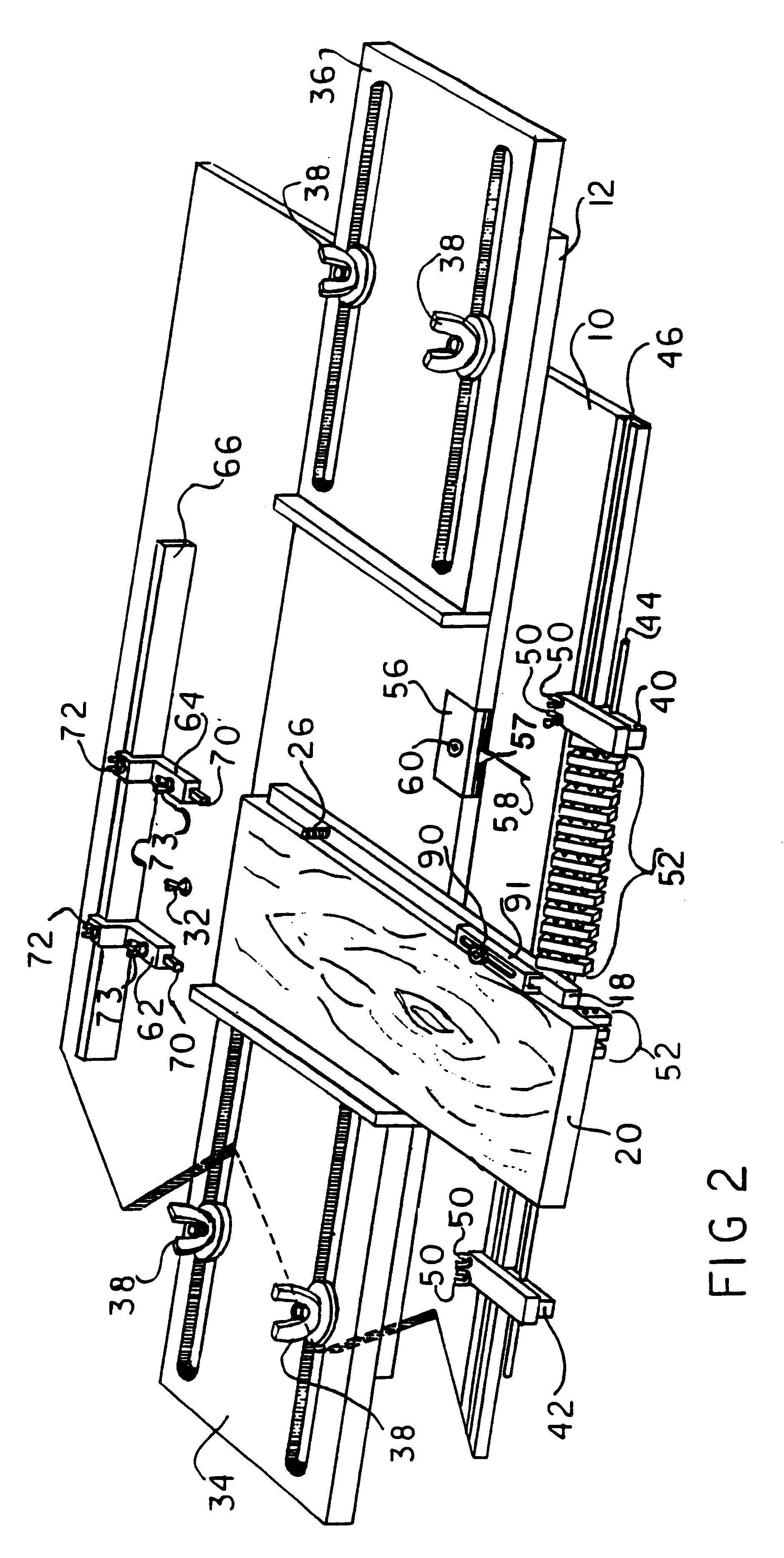
Jig system for positioning the placement of multiple cuts in a workpiece
a technology of multiple cuts and positioning joints, which is applied in the direction of tongue/groove making apparatus, manufacturing tools, instruments, etc., can solve the problems of inability to align the joints, the hole that is visible on the top surface of the drawer side, and the misalignment of joints, so as to reduce the lateral movement of the spacer and the effect of greater accuracy in positioning and cutting joints
- Summary
- Abstract
- Description
- Claims
- Application Information
AI Technical Summary
Benefits of technology
Problems solved by technology
Method used
Image

Examples
Embodiment Construction
The method of using the jig system of the present invention with a stationary cutting tool stabilized in a router table is best illustrated by the following example explaining the steps for cutting a hidden or half-blind dovetail joint on a pin workpiece 20 and a through dovetail joint on the rail workpiece 54.
Hidden dovetails are used on drawers where the drawer front (pin), when in the closed position, shows no evidence that the drawer was made using dovetail joints. When the drawer is opened, the dovetail joints are visible, but only on the drawer sides.
At least the drawer fronts (pins) are thicker than the drawer sides (rails) and this additional thickness hides the dovetails from frontal view.
For hidden dovetail joints, the depth of cut is set so that the top of the dovetail cutter is even with the top most surface of a drawer rail when a rail is laid flat on the surface of the sliding member. To accomplish this, the router was unplugged, the drawer rail was moved, side face up...
PUM
| Property | Measurement | Unit |
|---|---|---|
| angle | aaaaa | aaaaa |
| distance | aaaaa | aaaaa |
| movement | aaaaa | aaaaa |
Abstract
Description
Claims
Application Information