LCD device and method for fabricating the same having color filters and a resinous insulating black matrix on opposite sides of a counter electrode on the same substrate

a technology of counter electrodes and resinous insulating black matrix, which is applied in non-linear optics, instruments, optics, etc., can solve the problems of increasing the number of steps, reducing the display quality of the liquid crystal display device, and disturbing the orientation of the liquid crystal molecules

Inactive Publication Date: 2001-03-27
SHARP KK
View PDF9 Cites 27 Cited by
  • Summary
  • Abstract
  • Description
  • Claims
  • Application Information

AI Technical Summary

Problems solved by technology

This reduces the display quality of the liquid crystal display device.
Another problem is as follows.
This may disturb the orientation of the liquid crystal molecules.
This increases the number of steps, reduces the yield, and thus increases the production cost.
Moreover, when the stripe-shape counter electrodes are formed for a large-size and / or high-precision liquid crystal display device, the interconnection resistance of the counter electrodes increases, reducing the display quality.
Reverse tilt domains are generated due to a failure in the control of the orientation direction of liquid crystal molecules caused by a failure in the alignment processing during the step of forming an alignment film.
However, in the above-described structures of the active matrix substrate, although the generation of the reverse tilt domains is suppressed, the problem of the influence of slant components of the electric filed is not solved.
As a result, it is not possible to completely inhibit the generation of the reverse tilt domains.
Moreover, for a high-precision liquid crystal display device, a uniform charging is difficult, requiring the provision of a specific structure or step for interconnecting.
Fabricating such a liquid crystal display device increases the production cost.
In the regions corresponding to such spaces, it is not possible to apply a voltage to the liquid crystal layer to control the light blocking and transmission be the liquid crystal layer.
This tends to cause a short circuit therebetween, thereby reducing the production yield.
However, the following problem arises when the counter source structure shown in FIG. 10 is applied to a color liquid crystal display device.
In such a case, the orientation of liquid crystal molecules in the liquid crystal layer is disturbed in the vicinity of the steps, reducing the display quality.
If protrusions are formed between the colored portions, areas around such protrusions will become difficult to be rubbed desirably in a subsequent rubbing step.

Method used


Image

  • LCD device and method for fabricating the same having color filters and a resinous insulating black matrix on opposite sides of a counter electrode on the same substrate
  • LCD device and method for fabricating the same having color filters and a resinous insulating black matrix on opposite sides of a counter electrode on the same substrate
  • LCD device and method for fabricating the same having color filters and a resinous insulating black matrix on opposite sides of a counter electrode on the same substrate

Examples


example 2

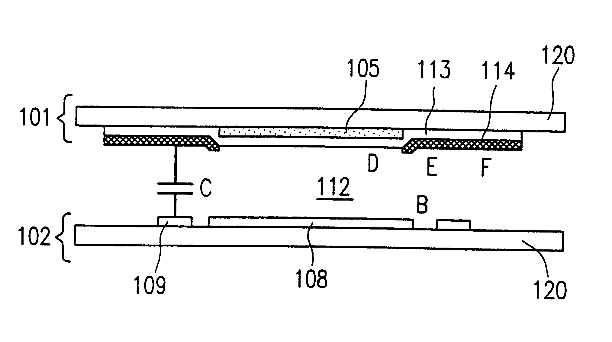
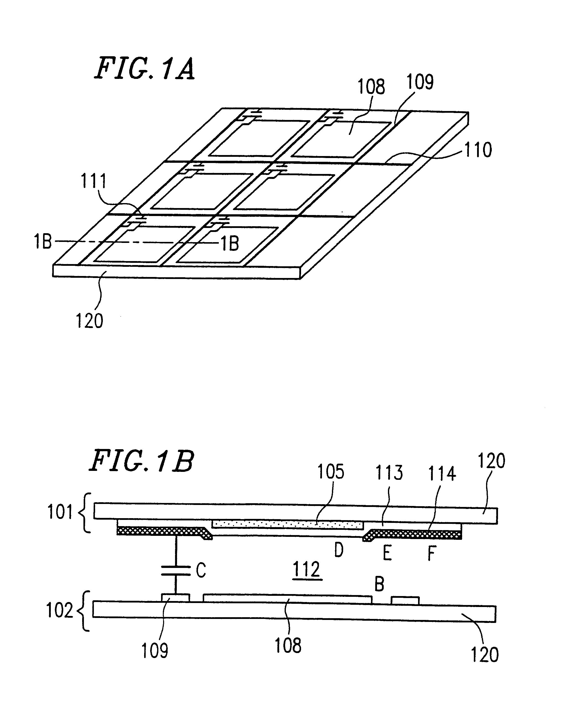
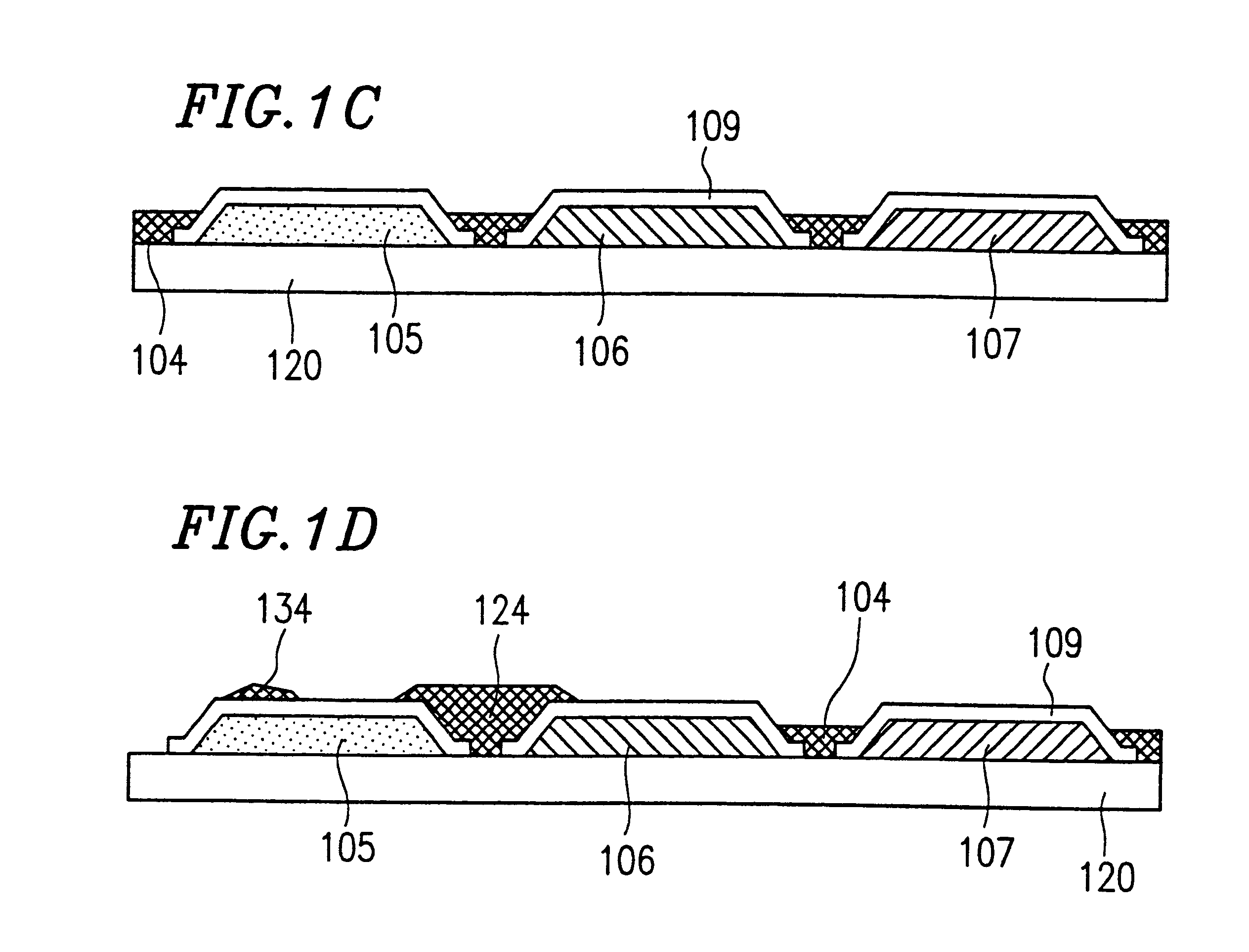
FIG. 1C is a sectional view schematically illustrating a first substrate (hereinbelow, referred to as a color filter substrate) of the liquid crystal display device of Example 2 according to the present invention.

The color filter substrate includes red (R) colored portions 105, green (G) colored portions 106, and blue (B) colored portions 107 formed on a glass substrate 120 at positions corresponding to pixel regions. Source bus lines 109 made of a transparent conductive film are formed over the respective colored portions. A black matrix (BM) layer 104 fills gaps between the colored portions overlapping peripheries of the colored portions.

The color filter substrate having the above structure is bonded with a second substrate including components as shown in FIG. 10, such as the pixel electrodes 1008 arranged in a matrix, the gate bus lines 1010 arranged in a direction crossing the source bus lines 109, the switching elements 1011, e.g., thin film transistors (TFTs), for selectively...


PUM

PropertyMeasurementUnit
diameteraaaaaaaaaa
thicknessaaaaaaaaaa
heightaaaaaaaaaa

Abstract

The liquid crystal display device of this invention includes a first substrate and a second substrate facing each other with a liquid crustal layer interposed therebetween, the first substrate including: color layers of different colors each having a plurality of colored portions; a transparent conductive film formed to cover the colored portions as a counter electrode; and a block matrix layer made of an insulating material for blocking light colored portions.

Description

1. Field of the InventionThe present invention relates to a liquid crystal display device used for displays of office automation apparatuses, audio and video apparatuses, and the like, and a method for fabricating such a liquid crystal display device.2. Description of the Related ArtA conventional transistor-type active matrix driven liquid crystal display device will be described with reference to FIGS. 6A and 6B, as the first prior art example. FIG. 6A is a perspective view of the conventional liquid crystal display device, and FIG. 6B is a sectional view taken along line 6B--6B of FIG. 6A.Referring to FIG. 6B, the conventional liquid crystal display device includes a first substrate 601 (hereinbelow, referred to as a counter substrate) and a second substrate 602 (hereinbelow, referred to as an active matrix substrate) disposed to face each other with a predetermined gap therebetween. A liquid crystal layer 612 is provided between the substrates 601 and 602. Referring to FIG. 6A, ...

Claims


Application Information

Patent Timeline
Patent Type & Authority Patents(United States)
IPC IPC(8): G02F1/13G02F1/1335G02F1/1345
CPCG02F1/133512G02F1/133516G02F1/1345G02F2201/121
Inventor TANAKA, KEIICHIYAMAMOTO, TOMOHIKO
Owner SHARP KK
Why Eureka
Try Eureka