MIL-STD-1553 buffer/driver

a buffer/driver and buffer technology, applied in the field of mil-std-1553 buffer/driver, can solve the problems of high data latency and messaging complexity, system will not tolerate an additional signal propagation delay of more than 2 microseconds, and bus performance to become marginal or undependabl

Inactive Publication Date: 2001-04-03
M TECHN
View PDF8 Cites 38 Cited by
  • Summary
  • Abstract
  • Description
  • Claims
  • Application Information

AI Technical Summary

Benefits of technology

11. Receives and retransmits a data signal through the bus buffer with a propagation delay of less than one microsecond, so that the use of the buffer in systems containing

Problems solved by technology

This system will therefore not tolerate an additional signal propagation delay of more than 2 microseconds.
There is a further need to permit the use of the 1553 standard in a system where the length of a single main bus, or the loading on it, might cause the bus performance to become marginal or undependable.
However, these devices hav

Method used


Image

  • MIL-STD-1553 buffer/driver
  • MIL-STD-1553 buffer/driver
  • MIL-STD-1553 buffer/driver

Examples


Embodiment Construction

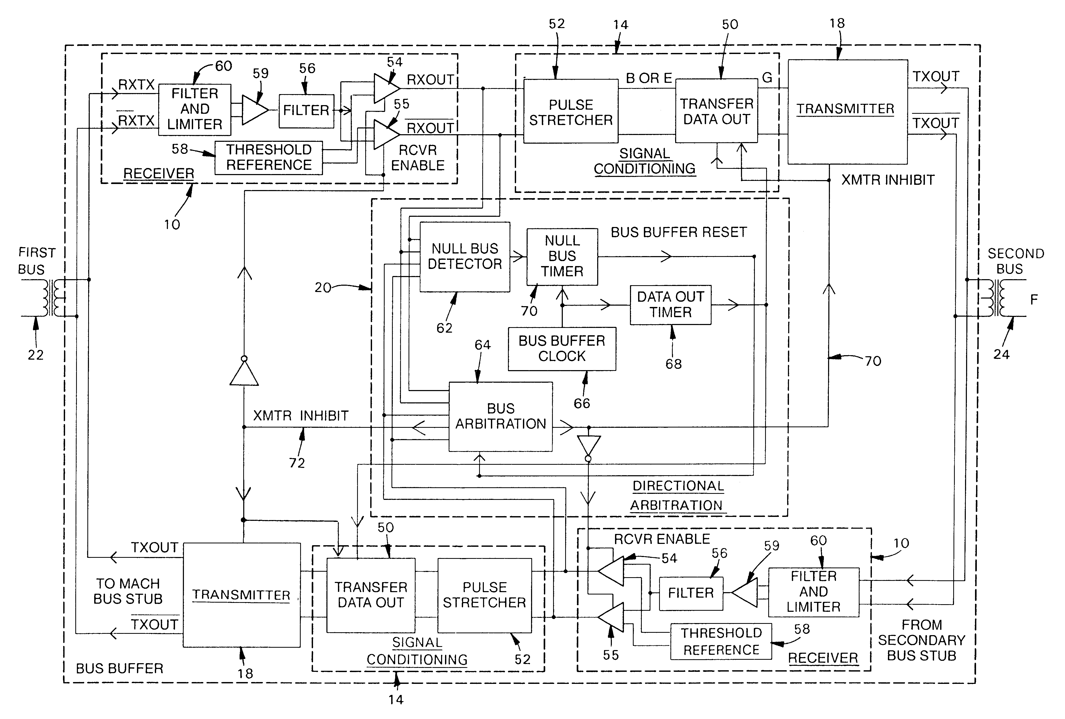
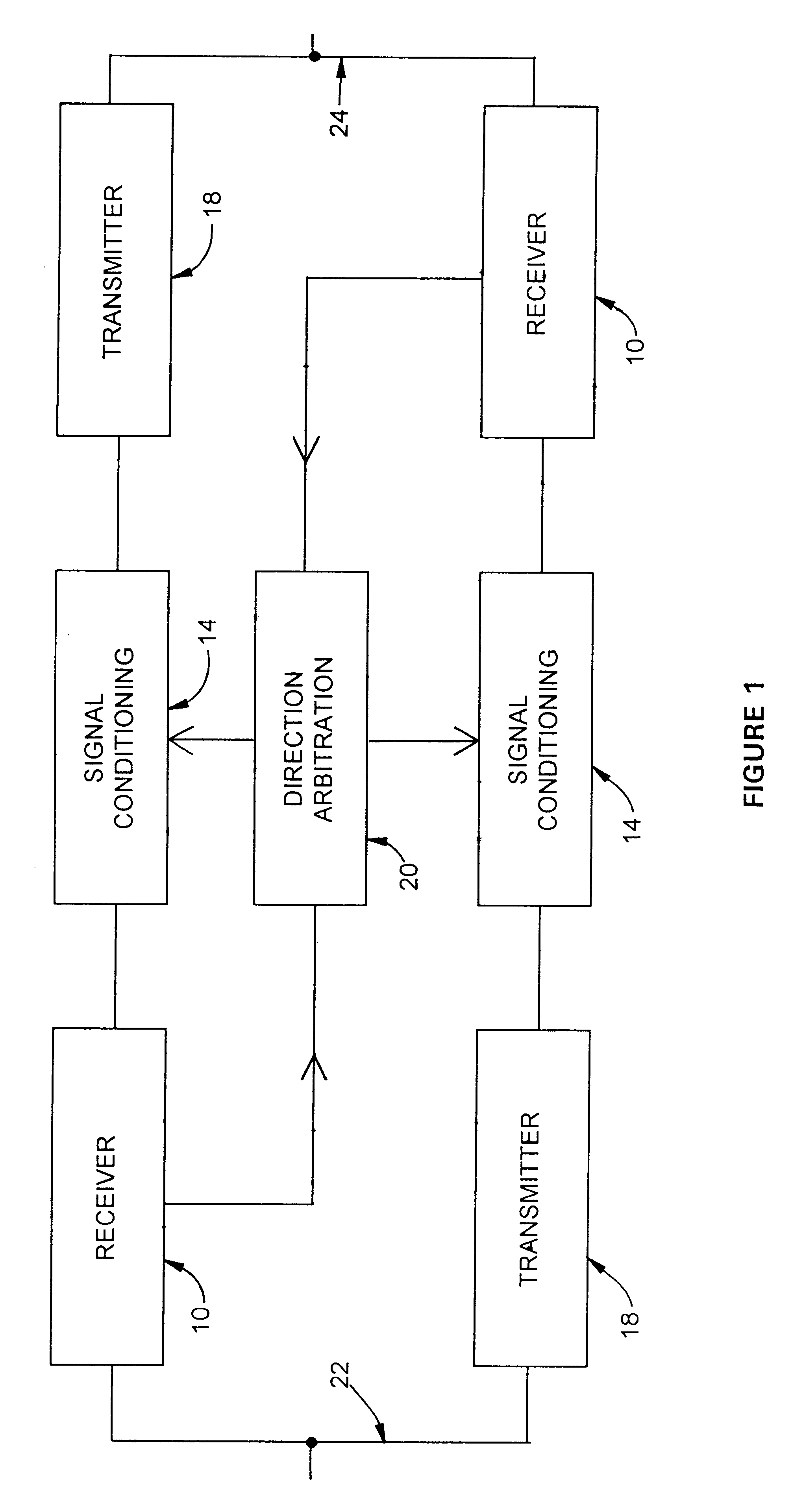
FIG. 1 is a block diagram of an embodiment of the present invention. This new device is symmetrical: data may flow from a first bus 22 to a second bus 24, or data may flow from a second bus 24 to a first bus 22. During operation, one of two receiver circuits 10 accepts Manchester II bipolar signals from a 1553 data bus and detects positive and negative portions of the Manchester II signal input that exceed a specified minimum magnitude. One of two signal-conditioning circuits 14 then reconstitutes the incoming signal and prepares the signal for one of two transmitters 18 with the time spacing of zero-crossings corrected. Direction arbitration logic 20 detects the presence of bus controller and remote terminal signals, determines their direction, and arbitrates bus direction so that signals may be transmitted through the buffer / driver in either direction.

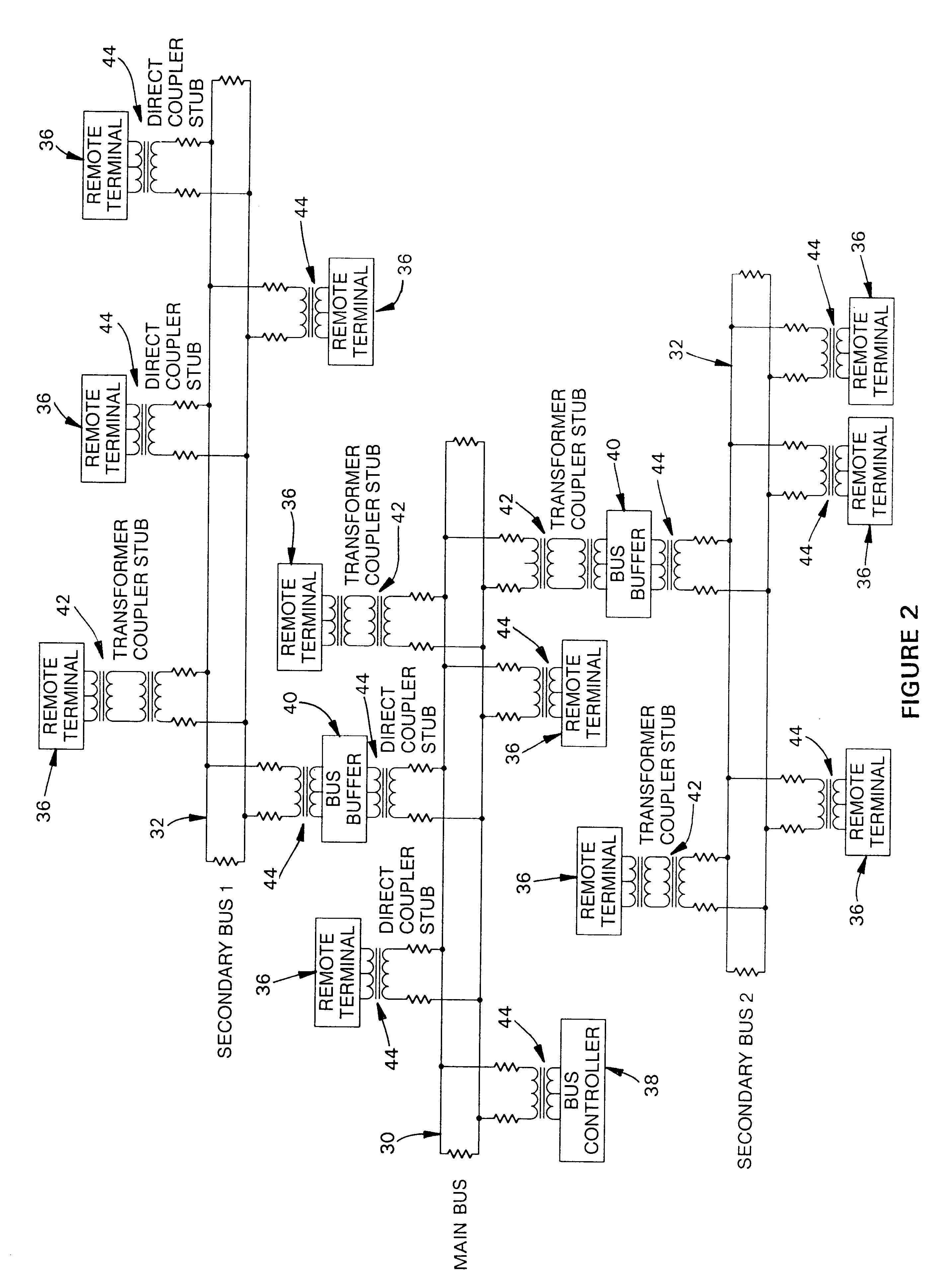
FIG. 2 shows the electrical interconnection of several buses using the present invention in a typical application. In this diagram,...


PUM


Abstract

A bus buffer conditions and amplifies bi-directional electrical signals on a line carrying MIL-STD 1553 bi-polar signals. The device includes a receiver with a threshold detector, a signal conditioner including a retiming circuit and an amplifying transmitter. The signal conditioner receives filtered bi-polar signal output from the receiver and transforms the signal into separate uni-polar digital outputs. The signal conditioner includes means for increasing the positive voltage state period of each uni-polar output voltage state until the beginning of the next output voltage state to eliminate an effective null bus period during a signal transmission. A timing circuit includes a clock and logic circuitry which retimes and combines the uni-polar signals to create a bi-polar digital output having retimed zero-crossing points which is then transmitted out to a second bus. Two bus buffers are connected between the first and second buses in reverse orientation to provide bidirectional capability. An arbitrator circuit sequences signals arriving at the device from both directions based on detection of a null bus period at either bus.

Description

This invention relates to digital logic design. More specifically, it relates to a bi-directional bus buffer that is designed to operate according to the specifications of the MIL-STD-1553B data bus standard. Reference may be made to "MIL-STD-1553B: Department of Defense Interface Standard for Digital Time Division Command / Response Multiplex Data Bus", Sep. 21, 1978.BACKGROUND OF THE INVENTION AND DESCRIPTION OF PRIOR ARTThe United States Department of Defense requires the use of MIL-STD-1553B as the standard for communications between electronic modules on all military airplanes and other vehicles. MIL-STD-1553B defines an asynchronous serial, command / response digital data bus on which messages are time division multiplexed among users. The 1553 STD specifies all of the electrical characteristics of receivers, as well as the complete message transmission protocol. The 1553 protocol specifies that all continuous data transfers start with a positive excursion of the wave form from a ...

Claims


Application Information

Patent Timeline
IPC IPC(8): H04L25/02
CPCH04L25/026H04L25/0266H04L25/0278H04L25/0286H04L25/0292
Inventor CAMMAROTA, JOSEPH P.MCGLYNN, EDWIN F.
Owner M TECHN
Why Eureka
Try Eureka