Visual display device

a visual display and warning device technology, applied in the direction of electric devices, static indicating devices, instruments, etc., can solve the problems of dangerous and annoying for the driver of the first vehicle, the driver of the front vehicle can also become distracted and/or temporarily blinded, and the virtual inability to warn other drivers

Inactive Publication Date: 2001-04-10
GENZEL BENNETT RALPH
View PDF16 Cites 26 Cited by
  • Summary
  • Abstract
  • Description
  • Claims
  • Application Information

AI Technical Summary

Problems solved by technology

However, there are other common types of situations in which it has been virtually impossible to warn other drivers when they are doing something which is distracting and/or dangerous to someone else.
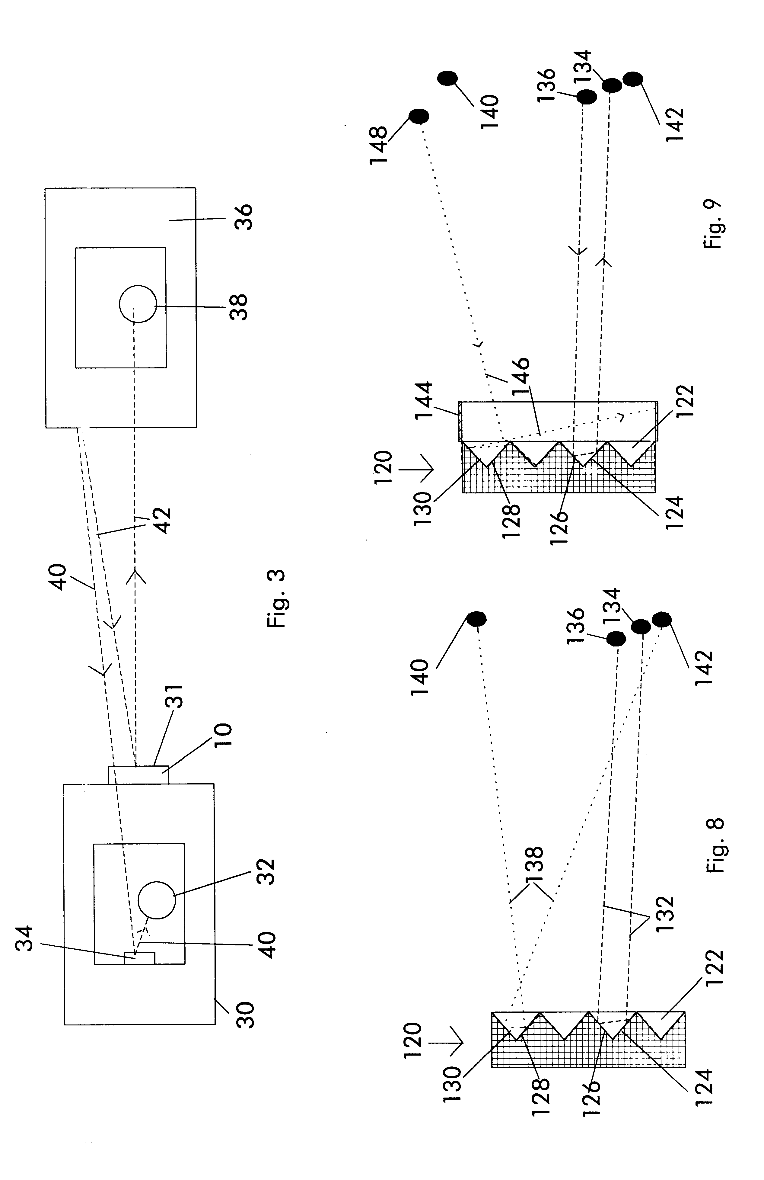
For example, when driving at night, the driver of a front vehicle can also become distracted and/or temporarily blinded by headlights from a following vehicle when they are reflected in the rear view mirrors of the front vehicle.
In any case, the situation is dangerous as well as annoying for the driver of the first vehicle because it interferes with his or her ability to see and react to road conditions.
First, the intensity of all reflected light is reduced, thereby significantly decreasing the driver's ability to observe other objects and his or her depth perception of the reflected images.
Second, such adjustable rear view mirrors are not generally mounted externally to the vehicle, and the driver can still be distract

Method used


Image

  • Visual display device
  • Visual display device
  • Visual display device

Examples


embodiment 60

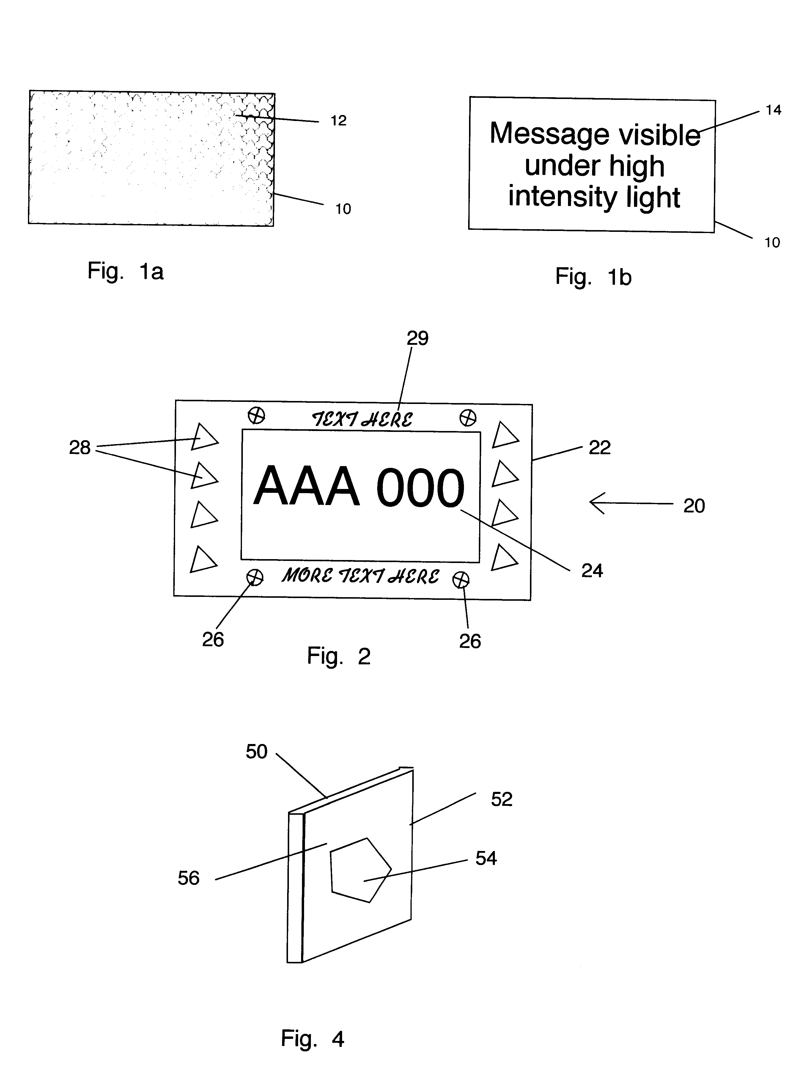
Another embodiment 60 of the present invention is shown in FIG. 5. A mask 62, having a pattern 64 and a background 66, and light filter 68 are sandwiched between a reflecting element 70, having a substantially smooth reflecting surface 72, and substantially transparent cover element 74. Mask 62 can be painted or printed onto surface 72, or it can be secured in contact with surface 72, or it can be secured in a spaced apart position relative to surface 72. Mask 62 can be formed from a combination of substantially opaque and substantially transparent materials arranged in pattern 64 and background 66. Alternatively, mask 62 can include a hologram, or it can include fluorescent or phosphorescent materials. Filter 68 can be a gray filter, transmitting a fraction of the light incident upon it over all visible wavelengths, or it can selectively transmit light over a range of visible wavelengths. Filter 68 can also include a diffraction grating. The device may include more than one filter,...


PUM


Abstract

A passive reflective device provides a warning or message visible when the intensity of light incident on the device exceeds a preselected minimum intensity or threshold value. The device includes a display, in the form of statements, pictographs, or images, with an appearance which is altered in color or pattern when impinged upon by light with an intensity greater than the threshold value and viewed by a viewer in front of the device. The device can be used as a sign or stationary display, such as a road sign, or it can be mounted on or in a front vehicle facing behind the vehicle such that the display is visible from behind the vehicle by someone who is within a preselected range of angles. The device can be mounted on the bumper or body of the vehicle, and the display can provide information, such as a visible warning to the driver of the following vehicle that his or her lights are shining so brightly on the front vehicle so as to cause the driver of the front vehicle to become uncomfortable, distracted, and/or temporary blind due to reflections of the following vehicle's headlights in the front vehicle's rear view mirror or mirrors. The device may have several appearances which change as the light intensity progressively exceeds several corresponding threshold intensities.

Description

1. Field of the InventionThe present invention is related generally to signs and visual warning devices which convey different information at different light intensity levels, and more particularly to a device which can be mounted on a motor vehicle and which conveys one or more messages when light of one or more predetermined intensities is incident upon the device.2. Description of Related ArtWhen driving a motor vehicle, it is often necessary and / or advisable to send a signal to other drivers to warn them of the presence or anticipated movements of the first vehicle. Devices commonly used to convey such signals include head lights, tail lights, and turn signal indicators. These types of signals are all intended to warn the driver of the following vehicle of actions of the front vehicle. Another type of signal which can be sent by a driver is to simply flash his or her vehicle's headlights to warn the driver of a vehicle approaching from the front that his or her headlights are to...

Claims


Application Information

Patent Timeline
IPC IPC(8): B60Q1/50G09F13/14
CPCB60Q1/50G09F13/14B60Q1/503
Inventor GENZEL, BENNETT RALPH
Owner GENZEL BENNETT RALPH
Why Eureka
Try Eureka