Magnetic lock device

a magnetic lock and magnetic technology, applied in the direction of magnets, magnets, snap fasteners, etc., to achieve the effect of increasing magnetic interaction, tightening and retaining the connection

Inactive Publication Date: 2001-04-10
APPL ART LAB
View PDF4 Cites 49 Cited by
  • Summary
  • Abstract
  • Description
  • Claims
  • Application Information

AI Technical Summary

Benefits of technology

It may be appreciated from the detailed description presented so far that the magnetic lock device according to the particular preferred embodiments and variation thereof has advantages over the conventional magnetic lock device whose usage is limited to bags, in that the magnetic lock device according to the present invention can be used not only with bags, but also with clothes that require regular and frequent washing or cleaning treatment. To provide those advantages, each of the first element and the second element may have an annular permanent magnet enclosed therein such that the permanent magnet and the other permanent magnet have the opposed polarities on the side facing opposite each other. And the first element may totally be covered with the non-magnetic, synthetic resin film, sheet, covering or casing or coated with the non-magnetic, synthetic resin layer. Alternatively, the first element and the second element may be covered with the non-magnetic, synthetic resin film, sheet, covering or casing or coated with the non-magnetic, synthetic resin layer, such that the ends of the first and seco

Problems solved by technology

But when the conventional magnetic lock device is used with clothing or clothes that may usually require the regular or frequent washing or cleaning treatment or that may often be put on the ground or make contact with other various objects, it is likely t

Method used


Image

  • Magnetic lock device
  • Magnetic lock device
  • Magnetic lock device

Examples


Embodiment Construction

The present invention is now described in further detail with reference to several preferred embodiments shown in the drawings.

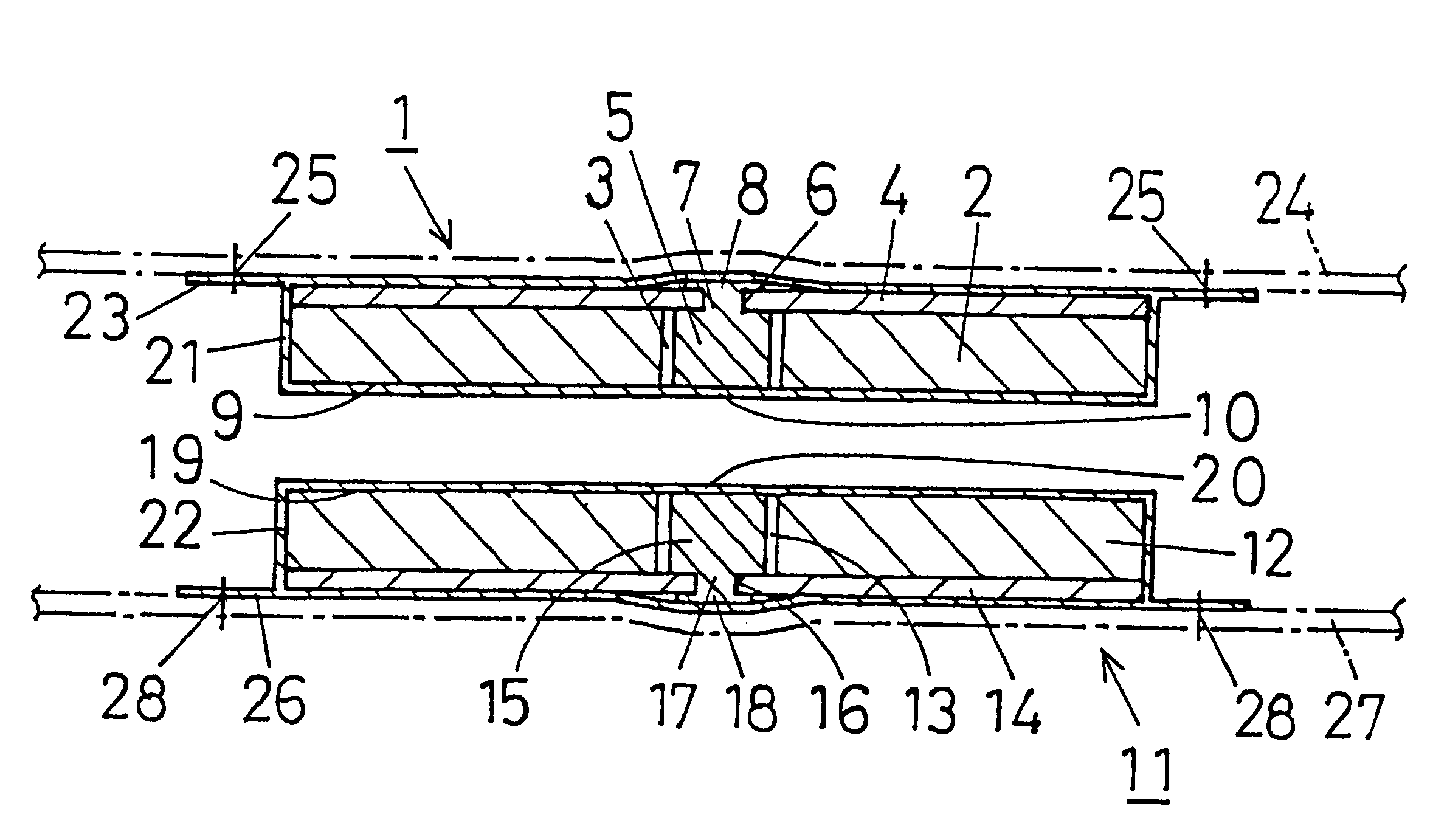
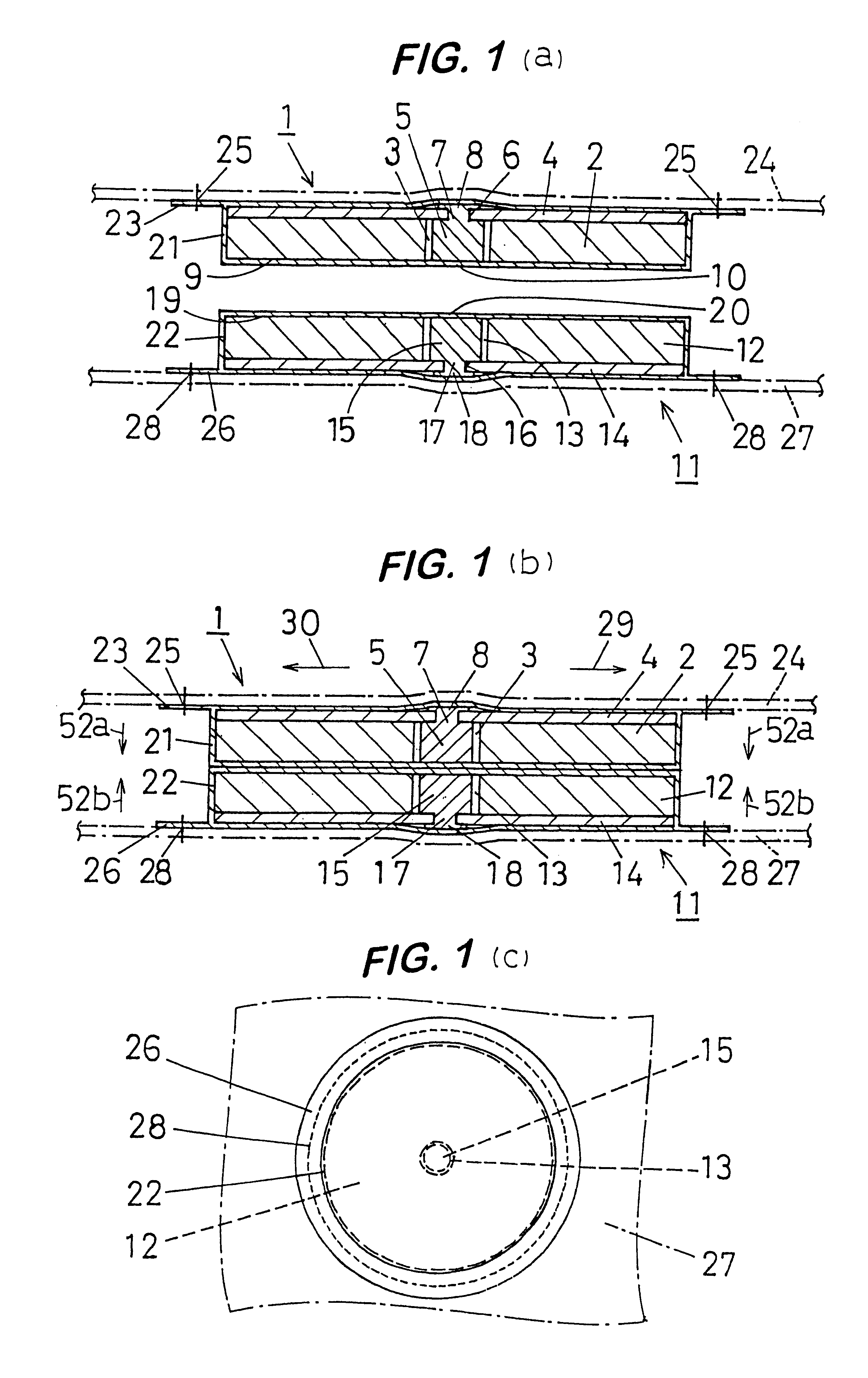
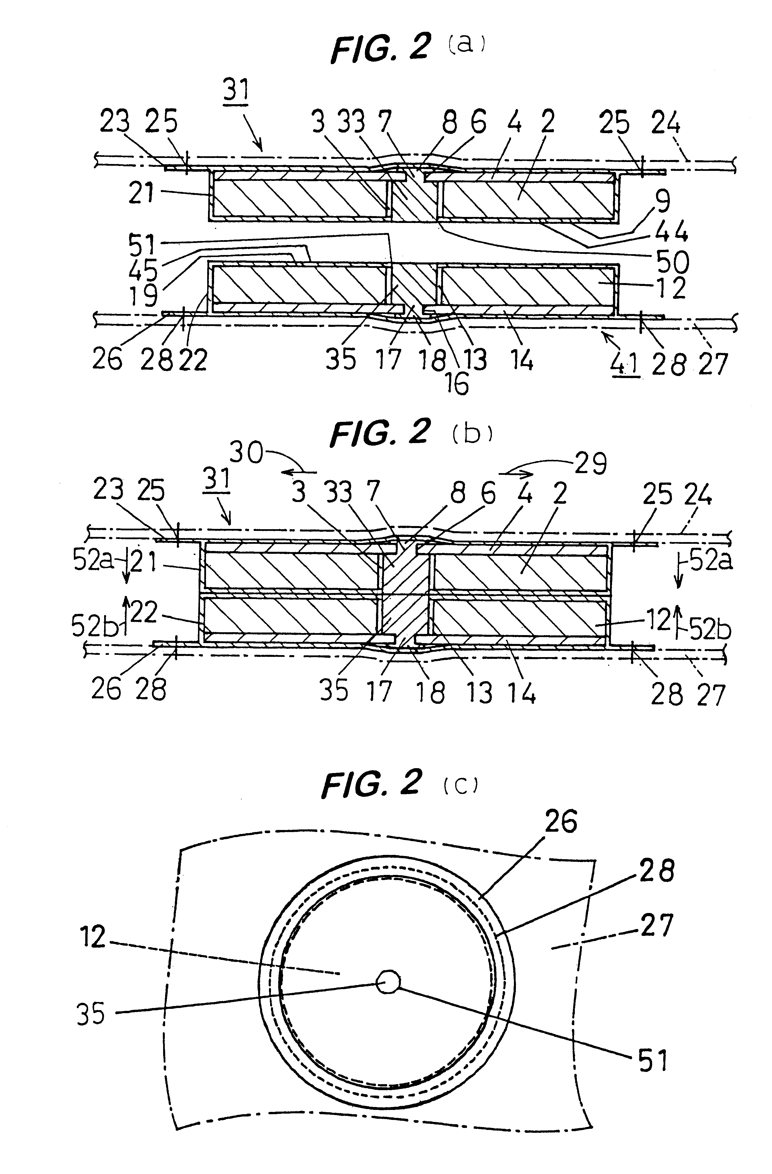
Referring first to FIG. 1, the magnetic lock device includes a first element 1 and a second element 11 that are capable of being detachably coupled together by the magnetic action. Specifically, the first element 1 includes a first annular permanent magnet 2 having a center bore 3 through it, a first ferromagnetic disk-like plate 4 that is provided to engage the non-attracting side of the first annular permanent magnet 2, and a first ferromagnetic projecting member 5 extending from the center of the first ferromagnetic disk-like plate 4 through the center bore 3 of the first annular permanent magnet 2 until it reaches the plane flush with the plane on the attracting side 9 of the first annular permanent magnet 2. Those component parts are incorporated as a single unit within a synthetic resin covering 21.

The second element 11 includes a second annular perman...


PUM


Abstract

A magnetic lock device includes a first element and a second element that are capable of being detachably coupled together by attracting each other magnetically under the magnetic interaction of permanent magnets, wherein each of the first and second elements includes an annular permanent magnet having a center bore through it, a ferromagnetic disk-like plate disposed to make contact with the permanent magnet, and a ferromagnetic projecting member extending from the disk-like plate and through the center bore of the permanent magnet. All of the component parts for the first and second elements are covered with any suitable synthetic resin film, sheet or the like and shielded from the outside, so that any foreign matter such as dust, particularly ferromagnetic particles like iron, cannot enter the gap or space that is present between the outer peripheral wall of the projecting member and the inner peripheral wall of the center bore through the annular permanent magnet. In one specific form of the magnetic lock device, each of the first and second elements is entirely covered with any suitable non-magnetic, synthetic resin film, sheet, covering or casing, or is entirely covered with a coating of any suitable non-magnetic, synthetic resin layer. In another specific form, each of the first and second elements is covered with any suitable non-magnetic, synthetic resin film, sheet, covering or casing, or is covered with a coating of any suitable non-magnetic, synthetic resin layer, except for the ends of the ferromagnetic projecting members in the first and second elements engaging each other that remain uncovered or exposed. In both forms, each of the first and second elements includes an annular permanent magnet, wherein one annular permanent magnet has a given polarity (S or N) opposed to the polarity (N or S) of the other annular permanent magnet on the side on which the first and second elements are to engage each other.

Description

FIELD OF THE INVENTIONThe present invention relates to a magnetic lock device including two separate elements that arc capable of being detachably coupled together by attracting each other magnetically under the magnetic interaction of two permanent magnets, and more particularly to a magnetic lock device that may be used with an article, such as bags, that usually includes two integral parts, such as a flap and a body, for detachably coupling those two parts together, and may also be used with clothing or clothes that usually require the regular or frequent washing or cleaning treatment.DESCRIPTION OF THE PRIOR ARTIn the prior art, there is a conventional magnetic lock device that takes advantage of the magnetic attracting action of a permanent magnet, and is used with an article such as a bag, for example, for detachably coupling the body and flap of the bag. It is known that this device performs well for the above purpose. The conventional magnetic lock device is known in differe...

Claims


Application Information

Patent Timeline
IPC IPC(8): A45C13/10E05C19/16E05C19/00H01F7/02E05B47/00
CPCA45C13/1069H01F7/0263E05C19/16E05B47/0038Y10T24/32Y10T292/11
Inventor AOKI, YOSHIHIRO
Owner APPL ART LAB
Why Eureka
Try Eureka