Coherent multiple beam laser system

Inactive Publication Date: 2001-04-10
THE UNITED STATES OF AMERICA AS REPRESETNED BY THE SEC OF THE AIR FORCE
View PDF2 Cites 30 Cited by
  • Summary
  • Abstract
  • Description
  • Claims
  • Application Information

AI Technical Summary

Benefits of technology

It is a further object of this invention to provide such a laser system which synchronizes the phase of the individual laser beam outputs, allowing these individual laser beams to be combined into a single coherent output beam.
It is a further object of this invention to provide such a laser system whic

Problems solved by technology

Today's industrial manufacturing lines are far more complex and automated than they were only a few years ago.
Unfortunately, as the power level of these lasers increases, so does their size and their cooling requirements.
As a result, these laser systems are very large in design and incorporate complex gas-transportation and heat-exchanging systems.
In addition to being exceptionally large, these laser systems are very complex in design and incorporate many moving parts, which make these systems very costly to design and install.
Besides the one-time cost associated with purchasing and installing these laser systems, they often require constant supervision and a high level of maintenance to keep them operating at peak efficiency.
Because of these factors, high power continuous wave or pulsed gas lasers are often unsuitable for a number of applications where mobility, size, weight or freedom from frequent service and

Method used


Image

  • Coherent multiple beam laser system
  • Coherent multiple beam laser system
  • Coherent multiple beam laser system

Examples


Embodiment Construction

Other objects, features and advantages will occur to those skilled in the art from the following description of a preferred embodiment and the accompanying drawings, in which:

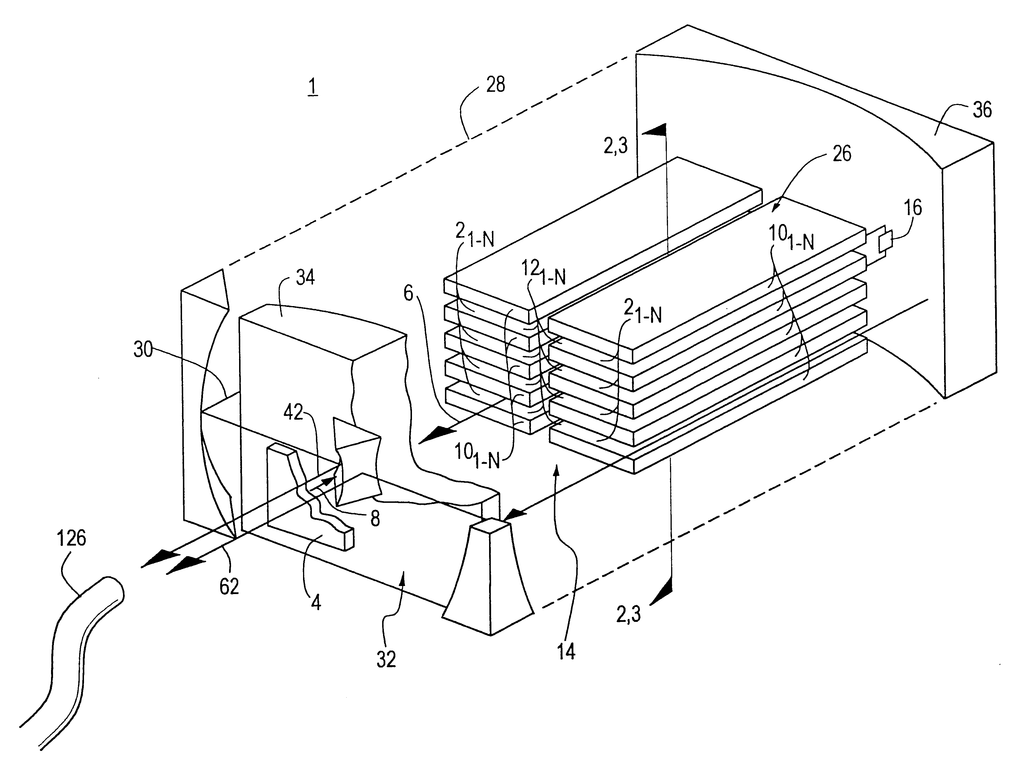
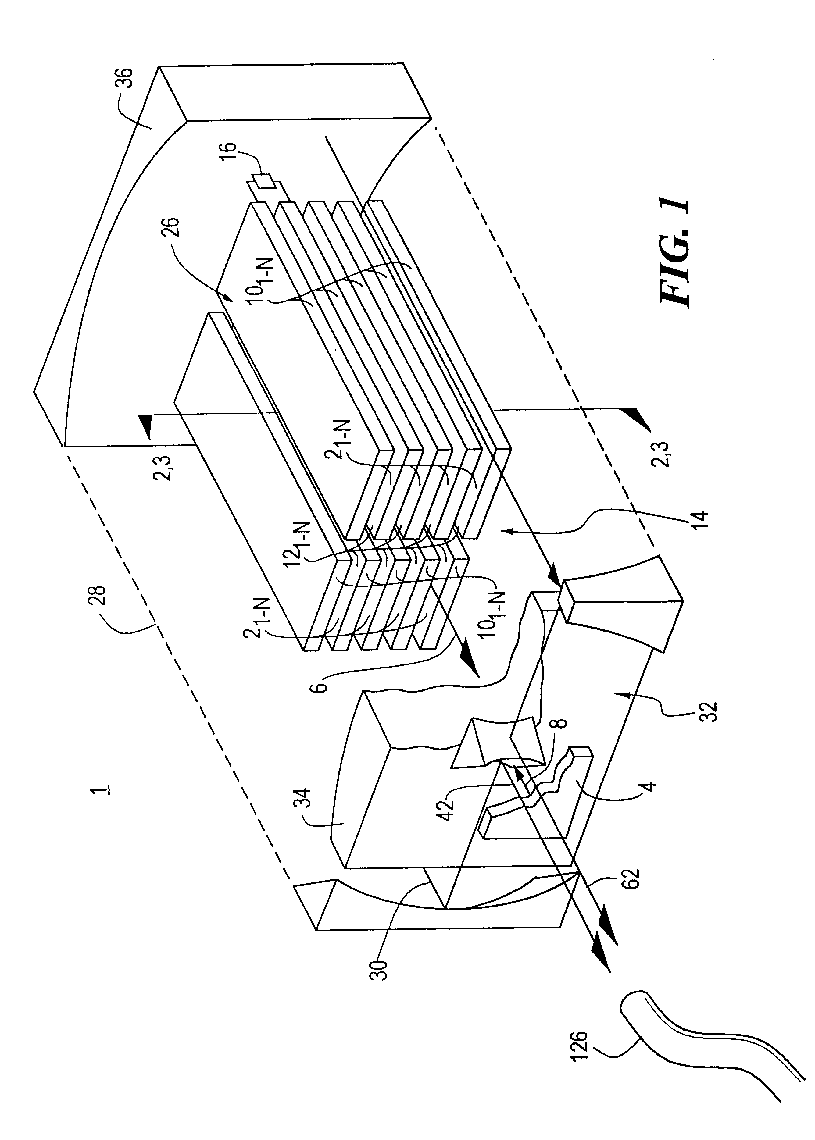
FIG. 1 is a three-dimensional view of the coherent multiple beam laser system of this invention in which a section of the resonant cavity has been cut away in order to show the arrangement of laser slabs;

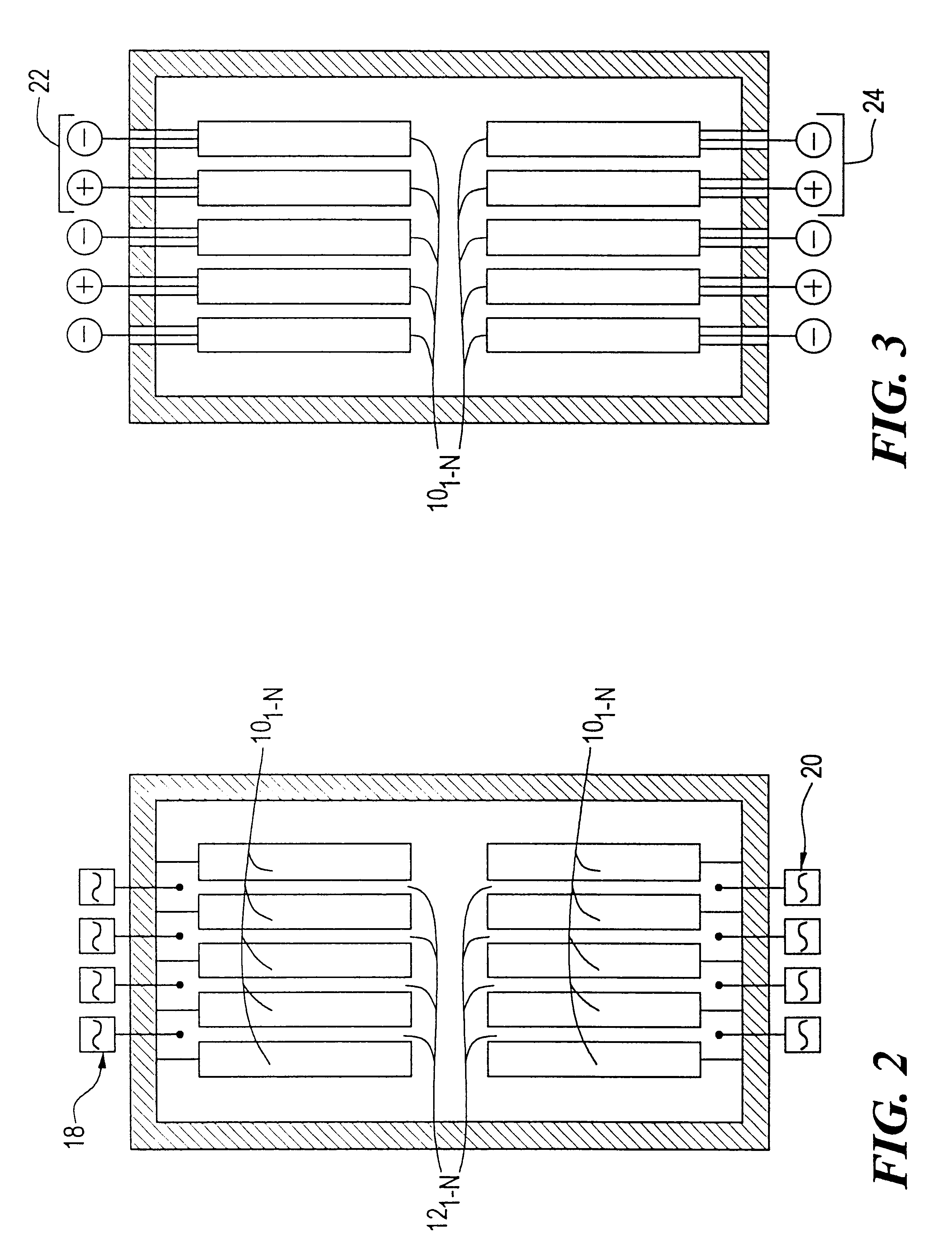
FIG. 2 is a cross-sectional view along line 2--2 of FIG. 1 showing the coherent multiple beam laser system of this invention including a plurality of RF / microwave slab excitation sources;

FIG. 3 is a cross-sectional view along line 3--3 of FIG. 1 showing the coherent multiple beam laser system of this invention, similar to FIG. 2, using AC / DC slab excitation sources instead of RF / microwave;

FIG. 4 is a cross-sectional view taken along line 4--4 of FIG. 5 of one embodiment of the coherent multiple beam laser system of this invention in which the individual laser beams generated within the resonant cavity exit adja...


PUM


Abstract

A coherent multiple beam laser system including a plurality of slab lasers and a feedback device responsive to the output of at least one of the slab lasers, for feeding back a portion of the slab laser output to the remaining slab lasers for synchronizing the phase of the outputs of all the slab lasers.

Description

This invention relates to a multiple beam laser system which is made coherent by combining and optically phase-locking multiple individual lasing medium outputs into a single coherent laser beam.BACKGROUND OF INVENTIONToday's industrial manufacturing lines are far more complex and automated than they were only a few years ago. Quite often, hi-tech manufacturing techniques have replaced the more traditional methods previously used. An example of this is the growing use of lasers during component prototyping and high volume manufacturing. Components that were traditionally cut with dies or flame cutters are often made with production lasers.When these production lasers are used to cut materials of considerable strength or thickness, such as plate steel, the energy level of the laser must be raised to provide the required cutting strength. Unfortunately, as the power level of these lasers increases, so does their size and their cooling requirements. High average power continuous wave (...

Claims


Application Information

Patent Timeline
IPC IPC(8): H01S3/23H01S3/06H01S3/10H01S3/07H01S3/08
CPCH01S3/2383H01S3/0606H01S3/07H01S3/08059H01S3/08068H01S3/08081H01S3/10092
Inventor REILLY, JAMES P.
Owner THE UNITED STATES OF AMERICA AS REPRESETNED BY THE SEC OF THE AIR FORCE
Why Eureka
Try Eureka