

Method for transparent heat insulation in building
- Summary
- Abstract
- Description
- Claims
- Application Information
AI Technical Summary
Benefits of technology
Problems solved by technology
Method used
Image

Examples
Embodiment Construction
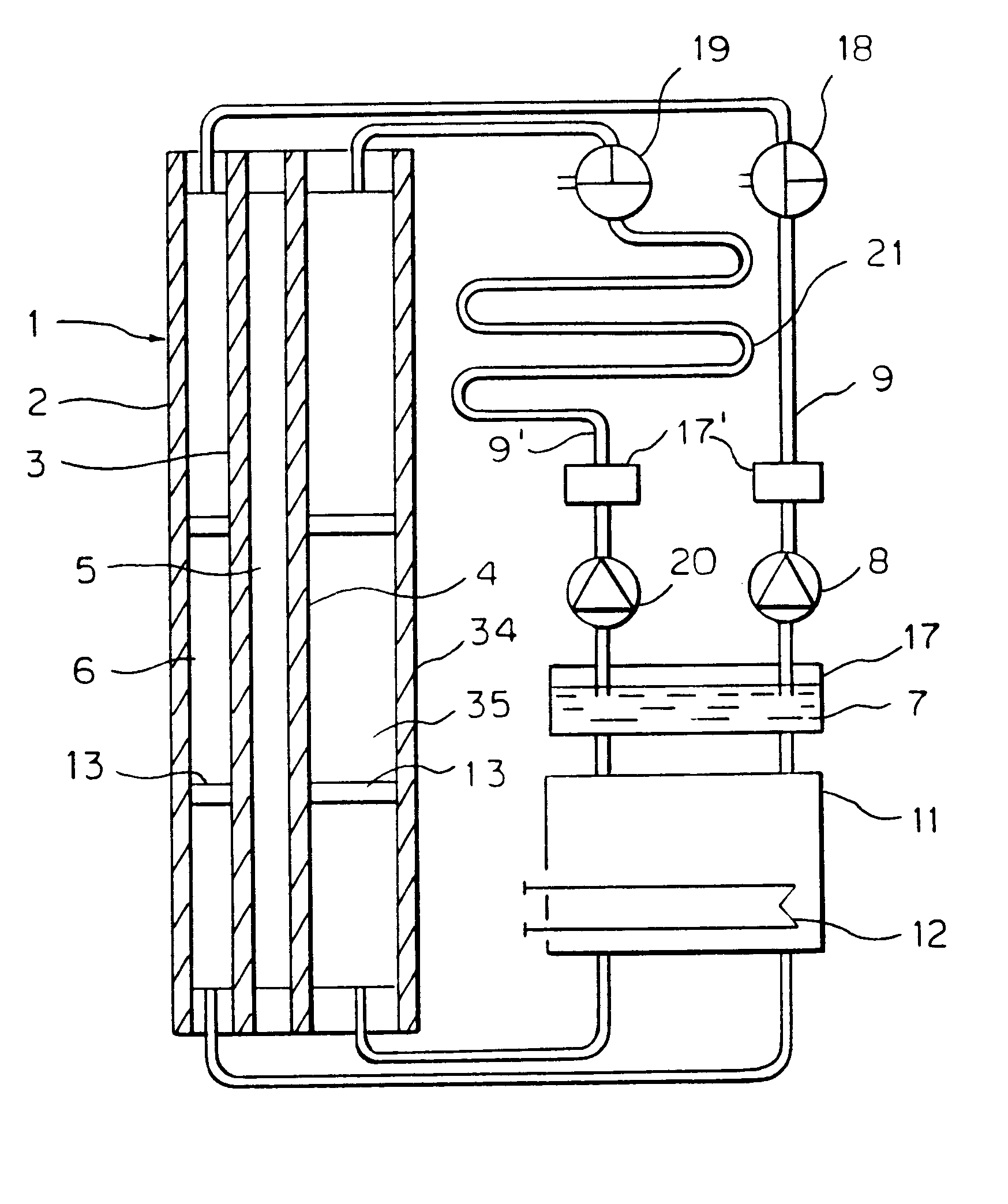
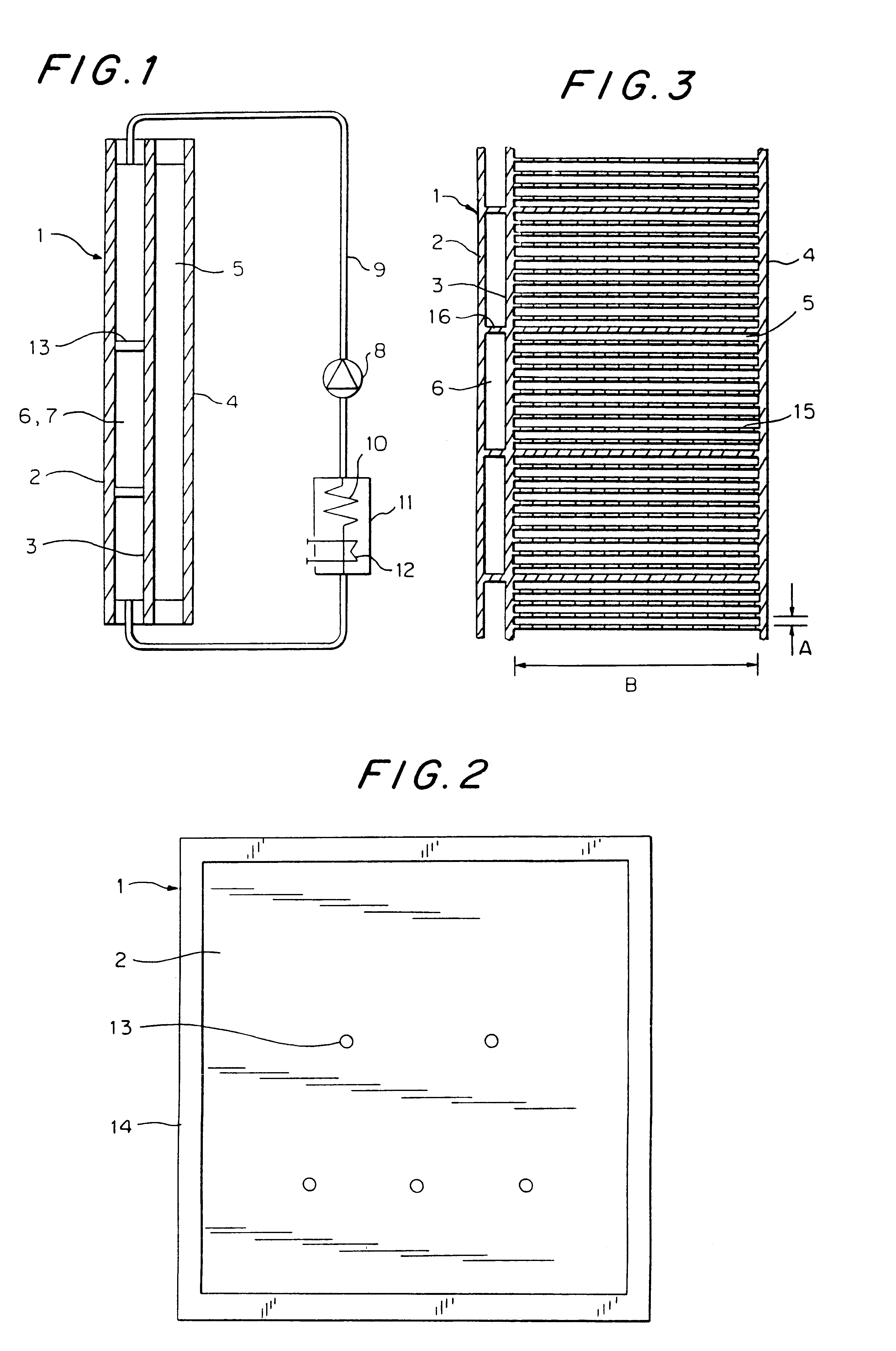
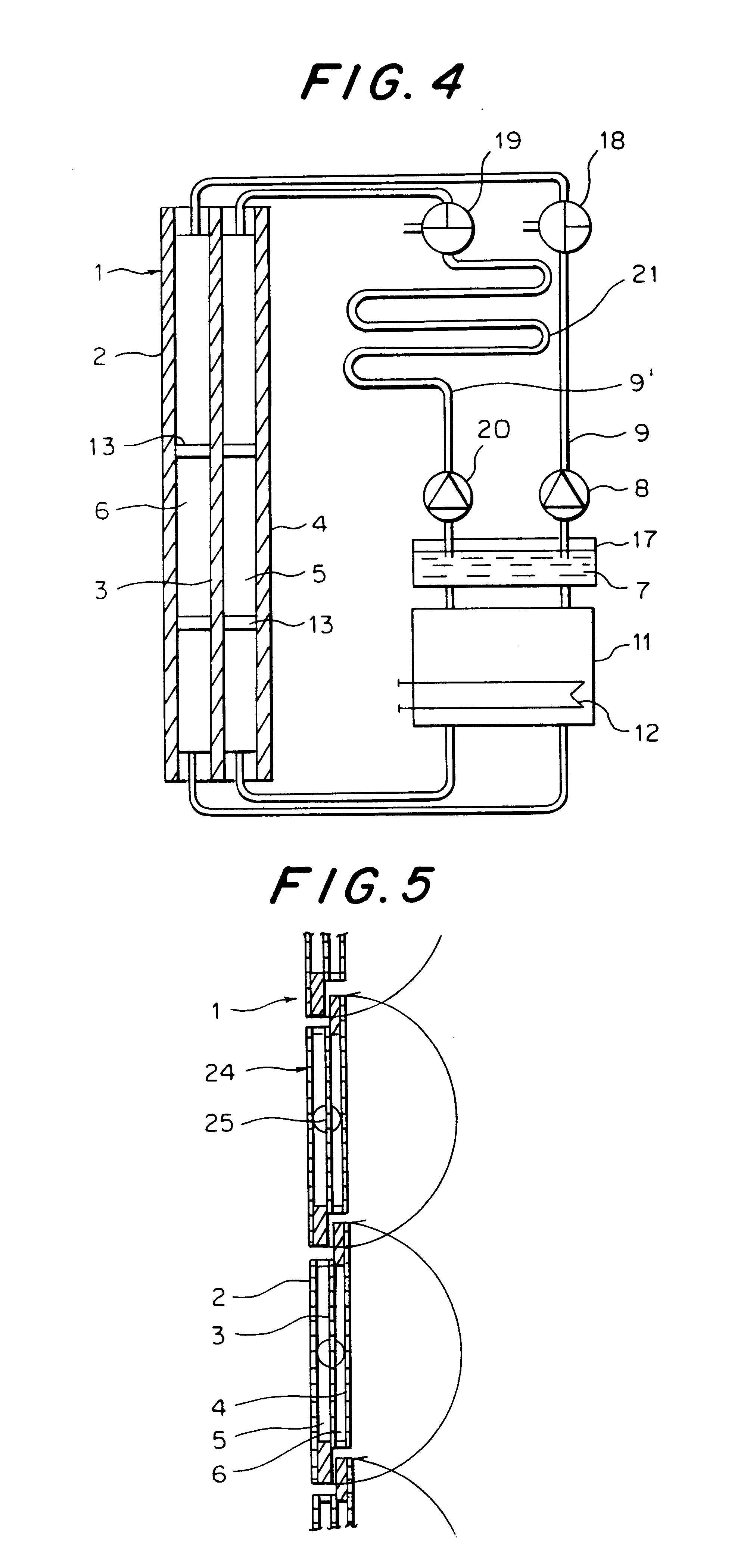
FIG. 1 shows a schematic cross-section through a facade element 1. It includes three parallel, transparent plates 2, 3, 4 comprising, for example, glass (triple-glazing). The plate 4 faces the interior of the building. The intermediate space 5 between the plates 3, 4 is filled with air or a different, better-insulating gas, and serves in heat insulation. The intermediate space 6 between the outer plate 2 and the center plate 3 is filled with a dyed or pigmented liquid 7. The selected dyeing or pigmentation allows light to pass through the liquid 7 practically unimpeded, but causes infrared light to be absorbed to the greatest possible extent. It is also possible, however, to attain a corresponding shading of the building interior through a more intense pigmentation and absorption of a portion of the visible light.
The liquid 7 in the intermediate space 6 circulates by means of a pump 8 and a ring circuit 9 that adjoins the intermediate space 6 at two oppositely-located sides. The hea...
PUM
 Abstract
Description
Claims
Application Information