Optical amplifying apparatus, an optical output controlling method by the optical amplifying apparatus, and an optical transmitting apparatus

a technology of optical amplifier and optical amplifier, applied in the direction of electromagnetic repeaters, transmission monitoring, electromagnetic transmission, etc., can solve the problems of degrading the optical output constant function of the optical amplifier, reducing the control of the optical amplifier output constant, and increasing the light output. , to achieve the effect of increasing the light outpu

Inactive Publication Date: 2001-04-17
FUJITSU LTD
View PDF5 Cites 27 Cited by
  • Summary
  • Abstract
  • Description
  • Claims
  • Application Information

AI Technical Summary

Benefits of technology

In the optical transmitting apparatus of this invention having an optical amplifying unit amplifying an optical signal inputted through an optical fiber and a receive signal processing unit performing a receive signal processing on the optical signal amplified by the optical amplifying unit, an optical signal at an excessive optical level is not generated when the optical signal is transmitted from the optical amplif

Problems solved by technology

When such protruding output light is generated in the optical amplifier used in an optical transmission system, the generated protruding output light (excessive output) is accumulatively amplified while passing through optical transmission paths, other repeaters and the like, the excessive output light is further increased when the terminal receives the optical signal, which exerts an effect on qualities of optical components receiving the optical signal in the receiving unit.
However, when a speed of the optical amplifier output constant control is decreased, the optical output constant function of the optical ampli

Method used


Image

  • Optical amplifying apparatus, an optical output controlling method by the optical amplifying apparatus, and an optical transmitting apparatus
  • Optical amplifying apparatus, an optical output controlling method by the optical amplifying apparatus, and an optical transmitting apparatus
  • Optical amplifying apparatus, an optical output controlling method by the optical amplifying apparatus, and an optical transmitting apparatus

Examples


first embodiment

Now, description will be made of this invention with reference to the drawings.

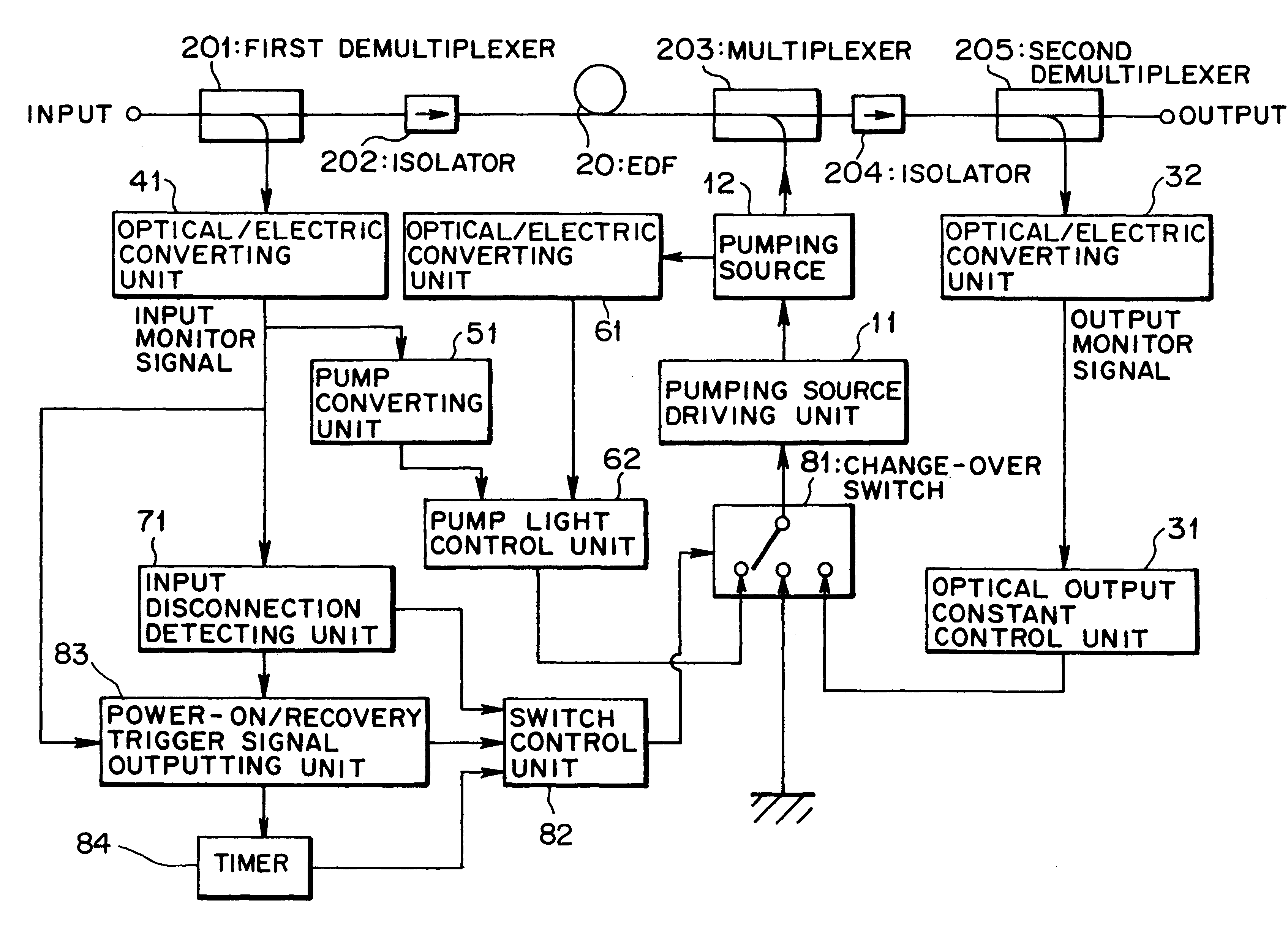
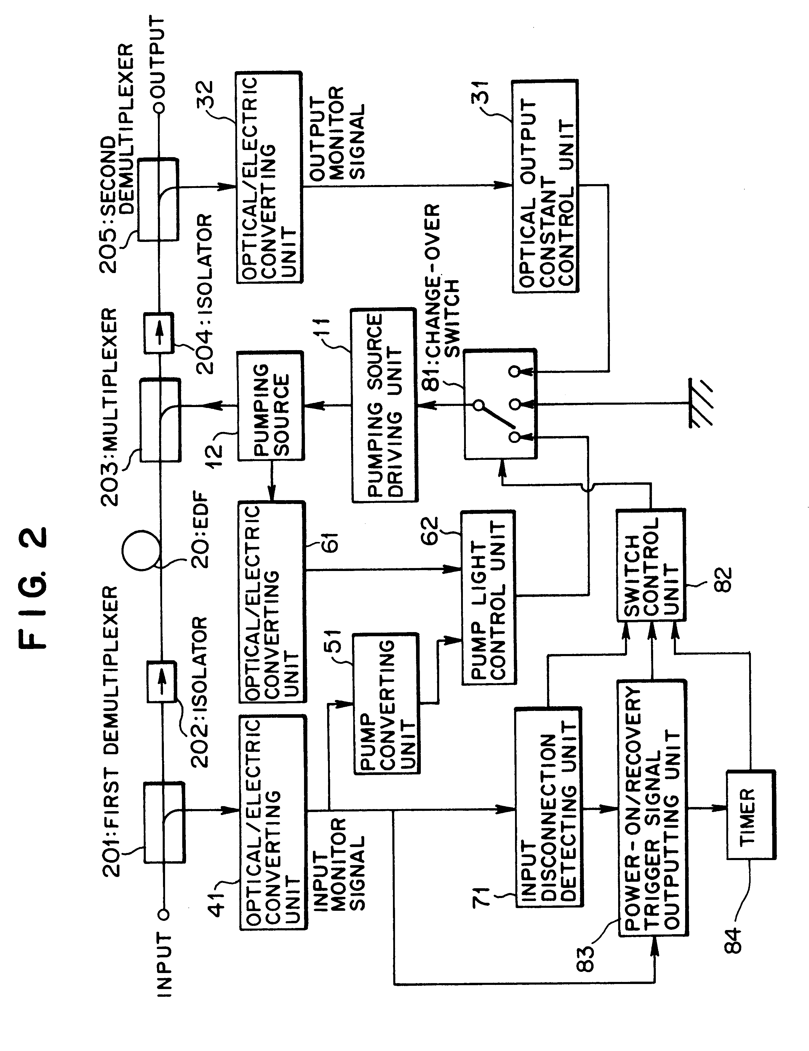
FIG. 2 is a block diagram showing a structure of an optical amplifying apparatus according to the first embodiment of this invention. The optical amplifying apparatus shown in FIG. 2 can be used in an optical transmitting apparatus 1000 in an optical transmission system transmitting an optical signal over a transmission path optical fiber as shown in FIG. 5, for example.

In the optical transmitting apparatus 1000 shown in FIG. 5, each of optical amplifying apparatus 100 and 100' has approximately the same structure as that of the optical amplifying apparatus shown in FIG. 2, which is used as an optical amplifying apparatus amplifying an inputted optical signal, detailed description of which will be described later.

The optical amplifying apparatus 100 functions as a high power amplifier for transmitting an optical signal, which corresponds to the optical amplifying unit amplifying a transmit signal generate...

second embodiment

(c) Description of the Invention

FIG. 6 is a block diagram showing a structure of an optical amplifying apparatus according to a second embodiment of this invention. The optical amplifying apparatus shown in FIG. 6 can be used in the optical transmitting apparatus 1000 in the above optical transmission system shown in FIG. 5.

The optical amplifying apparatus according to the second embodiment has, as shown in FIG. 6, a level comparing unit 87 and an optical output recovery level setting unit 88 instead of the timer 84 in the optical amplifying apparatus according to the first embodiment shown in FIG. 2. The other parts are similar to those of the optical amplifying apparatus according to the first embodiment. Incidentally, like reference characters in the drawing designate like or corresponding parts, descriptions of which are thus omitted.

An output monitor signal outputted from the optical / electric converting unit 32 is inputted to the level comparing unit 87. When a power-on / recover...

third embodiment

(d) Description of the Invention

FIG. 7 is a block diagram showing an optical amplifying apparatus according to a third embodiment of this invention. The optical amplifying apparatus shown in FIG. 7 can be used in the optical transmitting apparatus 1000 in the above optical transmission system shown in FIG. 5.

The optical amplifying apparatus according to the third embodiment has, as shown in FIG. 7, a current / voltage converting unit 63 in stead of the optical / electric converting unit 61 in the optical amplifying apparatus according to the first embodiment shown in FIG. 2, in which a signal inputted from the pumping source driving unit 11 to the pumping source 12 in also inputted to the current / voltage converting unit 63. The other parts are similar to those of the optical amplifying apparatus according to the first embodiment. Incidentally, like reference characters in the drawing designate like or corresponding parts, descriptions of which are thus omitted.

A part of a pumping source...


PUM


Abstract

An optical amplifying apparatus, an optical output controlling method by the optical amplifying apparatus and an optical transmitting apparatus, in which an optical output constant control is possible irrespective of an optical input level even when power-on is detected or an optical signal inputted after supply of pump light is stopped is recovered. The optical amplifying apparatus has an pump light outputting unit, an optical amplifier amplifying an input optical signal with pump light from the pump light outputting unit, an output constant control unit controlling the pump light outputting unit to keep a level of the amplified optical signal constant, an optical input monitoring unit, a pump light level setting unit setting an optical level of the pump light based on a result of optical input monitoring from the optical input monitoring unit, a pump light monitor control unit monitoring a level of the pump light to control the pump light outputting unit so as to stabilize an output level of the pump light at an optical level set by the pump light level setting unit, an input disconnection detecting unit, and an operation control switching unit switching a control mode for pump light to an output constant control mode, a pump light control mode or a stop control mode.

Description

(1) Field of the InventionThe present invention relates to an optical amplifying apparatus, an optical output controlling method by the optical amplifying apparatus, and an optical transmitting apparatus suitable for use to control an optical amplifier in an optical communication system.(2) Description of Related ArtAn optical fiber amplifier using an optical fiber doped with mainly a rare earth element such as erbium (Er) or the like has features of high gain, low noise, etc., which plays an important role in an optical transmission system as an optical amplifier amplifying an optical signal without converting the optical signal into an electric signal.In the optical transmitting system, the optical amplifier is required an optical output constant control to keep an optical output level constant in order to absorb a difference in level of optical inputs to the optical amplifier due to a difference in transmission path length.An optical amplifying apparatus performing the optical ou...

Claims


Application Information

Patent Timeline
IPC IPC(8): H01S3/13H01S3/067H01S3/131H01S3/06H01S3/10H04B10/07H04B10/29H04B10/293H04B10/564H04B10/572
CPCH01S3/1301H01S3/06754H01S3/0014H01S3/10015H01S3/1305H01S3/1001H01S3/13013
Inventor TAMURA, YUJI
Owner FUJITSU LTD
Why Eureka
Try Eureka