Damping top, damping rod, and damping device using same

a damping device and damping top technology, applied in the direction of liquid based dampers, shock proofing, mechanical instruments, etc., can solve the problems of reducing the accuracy of operation, and reducing the above mentioned conventional damping mechanism

Inactive Publication Date: 2001-05-15
SUMITOMO MITSUI CONSTR CO LTD
View PDF11 Cites 40 Cited by
  • Summary
  • Abstract
  • Description
  • Claims
  • Application Information

AI Technical Summary

Problems solved by technology

The above mentioned conventional damping mechanism, however, has difficulties to be described below.
Such the hinge-leverage means is, however, insufficient in amplifying magnification (rate in increase of t

Method used


Image

  • Damping top, damping rod, and damping device using same
  • Damping top, damping rod, and damping device using same
  • Damping top, damping rod, and damping device using same

Examples


Embodiment Construction

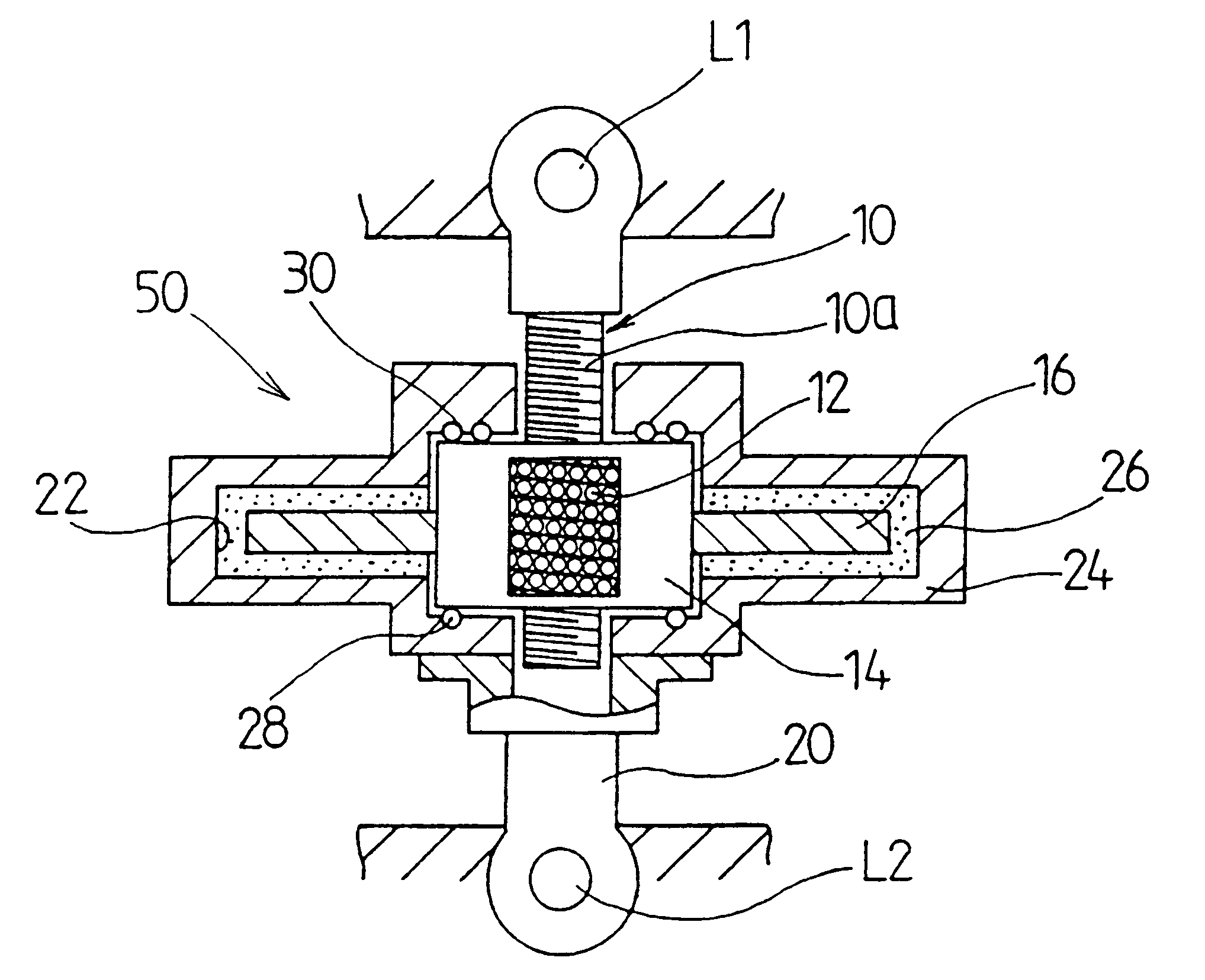
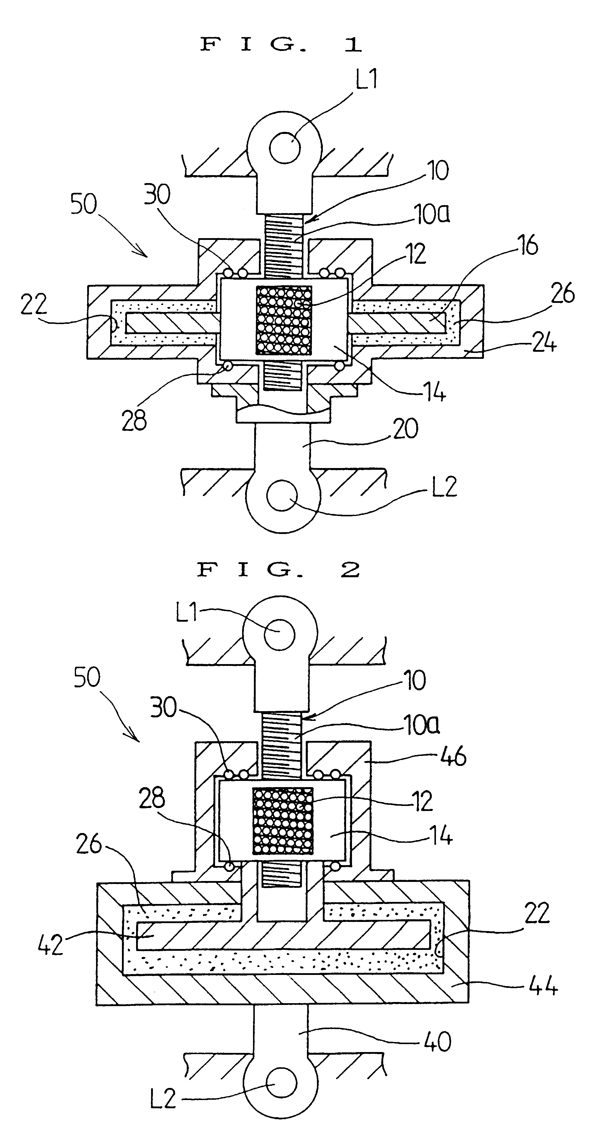
The damping top of the first embodiment in accordance with the present invention will hereinafter be described with reverence to the attached drawings. In FIG. 1, the damping device in accordance with the present invention may basically comprise first and second connective members so coupled with each other as to connect two points (objects) L1 and 12 relatively displacing from one another. Namely, the damping device comprises a first rod 10 and a tube-shaped second rod 20. Those rods 10 and 20 are connected through those ends to the two points L1 and L2 respectively. The first rod 10 has a connective part formed of a screw portion 10a to which a guide nut 14 is engaged through ball bearings 12, and a rotational top 16 is attached to the guide nut 14 so that the rotational top 16 is rotatable and slideable over the screw portion 10a. The second rod 20 is formed in its connecting side with a casing 24 defining a chamber 22 which accommodates the above rotational top 16, so that a dam...


PUM


Abstract

A damping top which comprises first and second L1 connection members (10, 20) connected to each other so as to connect two relatively displacing points (objects) (L1, L2) to each other, which connection members are fixed at one end thereof to the two points (L1, L2), respectively. The first connection member (10) is formed at its connection side with a guide screw portion (10a), on which is rotatably and slidably mounted a rotating top (integral rotating unit) (16) adapted to be driven by a guide nut (14) threaded onto the screw portion through a ball bearing (12). The second connection member (20) is formed at its connection side in a casing (24) for a chamber (22), which receives therein the rotating top (16), and a damping viscous body (26) is filled in the chamber (22). Thus it is possible to provide a damping device which is simple and small-sized, and provides great damping effects.

Description

The present invention relates to a damping top (damping mechanism), a damping rod and damping devices using the same which have simple structures and small sizes and also are capable of providing great damping effects.BACKGROUND OF THE ARTIn general, the damping mechanism is provided between two points (objects) relatively displacing to each other, so that a vibration energy to be transferred from one vibration source side to other damping object side is converted into a thermal energy for causing the vibration energy to disappear, thereby achieving the damping effects.The above mentioned damping mechanism is so structured that parts relatively displacing to each other by vibration are accommodated in a chamber including a viscous material, which is formed in the device, whereby the damping effect is achieved through its viscous and frictional resistance, and further in this case so structured that an amount of displacement of the above mentioned relatively displacing parts is ampli...

Claims


Application Information

Patent Timeline
IPC IPC(8): E04H9/02F16F9/12F16F15/023F16F9/10
CPCE04H9/02F16F9/12F16F15/0235E04H9/028E04H2009/026F16F2232/06E04H9/0235E04H9/0237
Inventor KURODA, EIJIARIMA, FUMIAKIHATA, TAMOTSUKIMIJIMA, HIDEO
Owner SUMITOMO MITSUI CONSTR CO LTD
Why Eureka
Try Eureka