Method and circuit arrangement for determining an optimum gain for the integrator of a speed controller

a technology of integrator and integrator, which is applied in the direction of controllers with particular characteristics, adaptive control, instruments, etc., can solve the problems of affecting the stability of the controller, requiring the entire controller structure to be altered, and requiring the presence of optimal starting values

Inactive Publication Date: 2001-05-22
DR JOHANNES HEIDENHAIN GMBH
View PDF20 Cites 17 Cited by
  • Summary
  • Abstract
  • Description
  • Claims
  • Application Information

AI Technical Summary

Problems solved by technology

Thus, controller parameters are not optimized, and the adjusted frequency range can shift under different load conditions, which can lead to damaging oscillation in the controlled subassemblies.
A drawback of this system is that it requires that the entire controller structure be altered.
This design has the disadvantage that optimal starting values must already be present in order to have a stable operation.
The disadvantage of this scheme is that when the gain in the integral branch is adjusted, oscillations experienced by the mechanical components coupled to the electro-motor do not decay quickly in the measuring interval.
As a result, an excessively low gain exists on a regular basis in the integral branch.
This unnecessarily degrades the dynamic response of the entire system that includes the control loop and the machine components.

Method used


Image

  • Method and circuit arrangement for determining an optimum gain for the integrator of a speed controller
  • Method and circuit arrangement for determining an optimum gain for the integrator of a speed controller
  • Method and circuit arrangement for determining an optimum gain for the integrator of a speed controller

Examples


Embodiment Construction

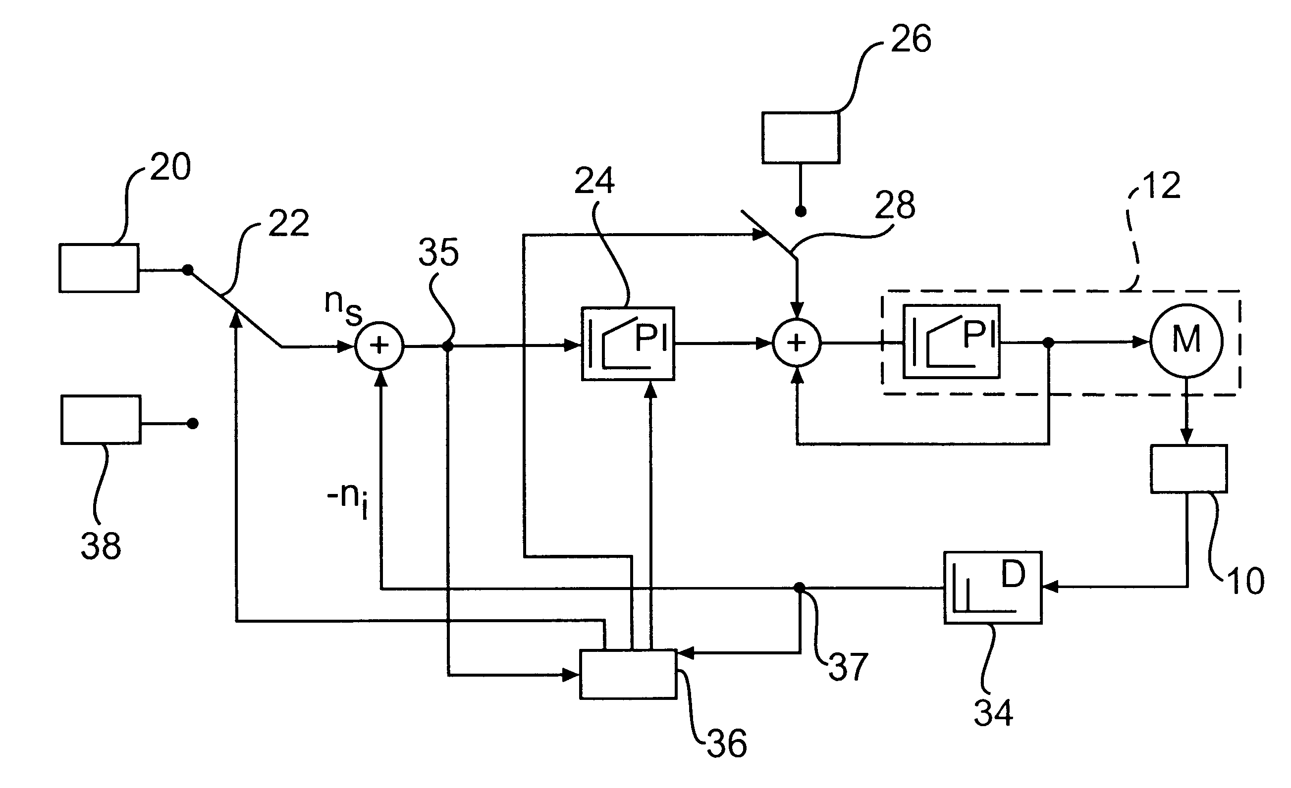
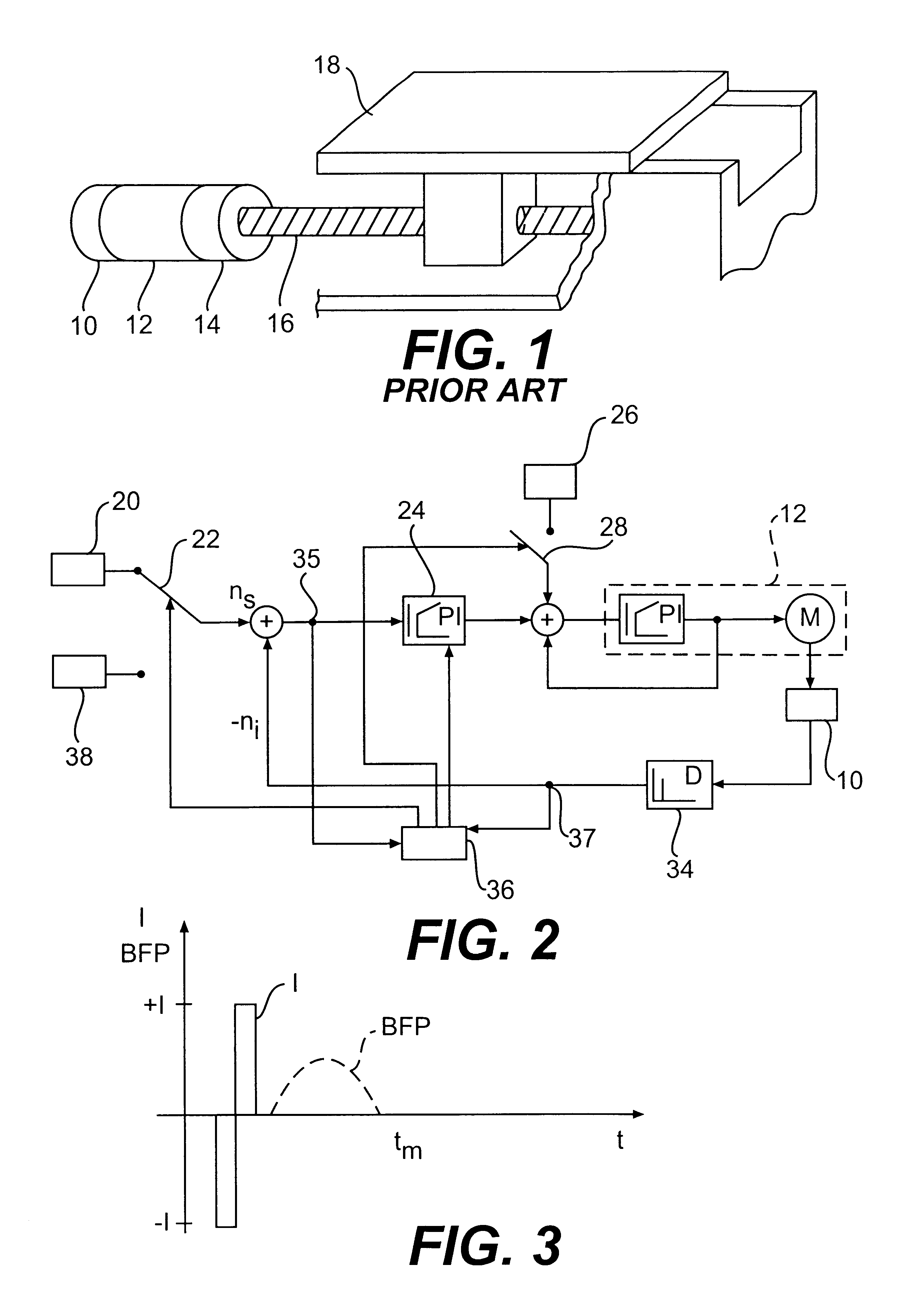
In the following description, it is assumed that the method according to the present invention for determining optimum controller parameters is applied to an automatic speed control for a servo motor of a machine-tool. However, it would be evident to one skilled in the art that the method according to the present invention can also be used for any other electro-motor, such as a spindle-drive motor, which is integrated in a mechanical arrangement and whose rotational speed needs to be controlled quickly to reach a set rotational speed.

The method for determining controller parameters described in German Patent DE 197 34 208 of the applicant is included in the method of the present invention, and is described again in detail.

FIG. 1 depicts an example of a driving assembly, in which an electro-motor 12 is coupled to a rotary position transducer 10 and to other mechanical subassemblies, such as to a subassembly 14, which can contain a brake, a coupling, and a gear unit for electro-motor ...


PUM


Abstract

A method for determining optimum controller parameters for a digital rotational speed control is described, in which various test signals are applied to a speed control loop and the resulting speed characteristic is determined. The speed characteristic is subsequently weighted with respect to rise time and transient response for various controller parameters, and the most favorable controller parameters are subsequently set in the controller of the control loop. The integral-action time of the control loop is used as a criterion in performing the weighting operation.

Description

The present invention relates to a method for determining the optimum gain for the integral-action component of a closed-loop or automatic speed control.DESCRIPTION OF RELATED ARTU.S. Pat. No. 5,157,597, describes a method to detect oscillations in servo system operation and to modify the loop gain of closed loops. In the process, a characteristic ratio is fixed between the position-control-loop gain and the position deviation in such a way that the loop gain assumes a large value for certain position deviation values. The position deviation is periodically determined during operation, and the main oscillation component of the position deviation is determined. The loop gain of the servo system is adjusted in such a way that the main oscillation component falls within a specified frequency range.In this scheme, however, although the frequency range in which the servo system begins to oscillate is adjusted, the tendency to oscillate is not diminished. Thus, controller parameters are n...

Claims


Application Information

Patent Timeline
Patent Type & Authority Patents(United States)
IPC IPC(8): G05B13/02
CPCG05B13/024
Inventor KERNER, NORBERT
Owner DR JOHANNES HEIDENHAIN GMBH
Why Eureka
Try Eureka