Electrochemical oxidation of hydrogen sulfide

a hydrogen sulfide and electrochemical technology, applied in the direction of electrodes, fuel cells, photographic processes, etc., can solve the problems of hydrogen sulfide, corrosive and extremely toxic gas, gas streams containing hydrogen sulfide,

Inactive Publication Date: 2001-06-05
ETHYL TECH
View PDF8 Cites 39 Cited by
  • Summary
  • Abstract
  • Description
  • Claims
  • Application Information

AI Technical Summary

Problems solved by technology

Hydrogen sulfide (H.sub.2 S) is a corrosive and extremely toxic gas that is present in natural gas wells at concentrations ranging from a few ppm to 50% or even higher.
Hydrodesulfurization of heavy oil and bitumen and coal gasification also produce gas streams containing hydrogen sulfide as an undesirable by-product.
Although the Claus process is exothermic and generates thermal energy, the heat is generally not utilized and therefore has no economic value.
Neither this, nor other approaches recovering hydrogen using thermal catalytic decomposition and membranes for separation, has been commercialized yet, which is partly due to an overall net energy input being required.
The proble

Method used


Image

  • Electrochemical oxidation of hydrogen sulfide
  • Electrochemical oxidation of hydrogen sulfide
  • Electrochemical oxidation of hydrogen sulfide

Examples


example 2

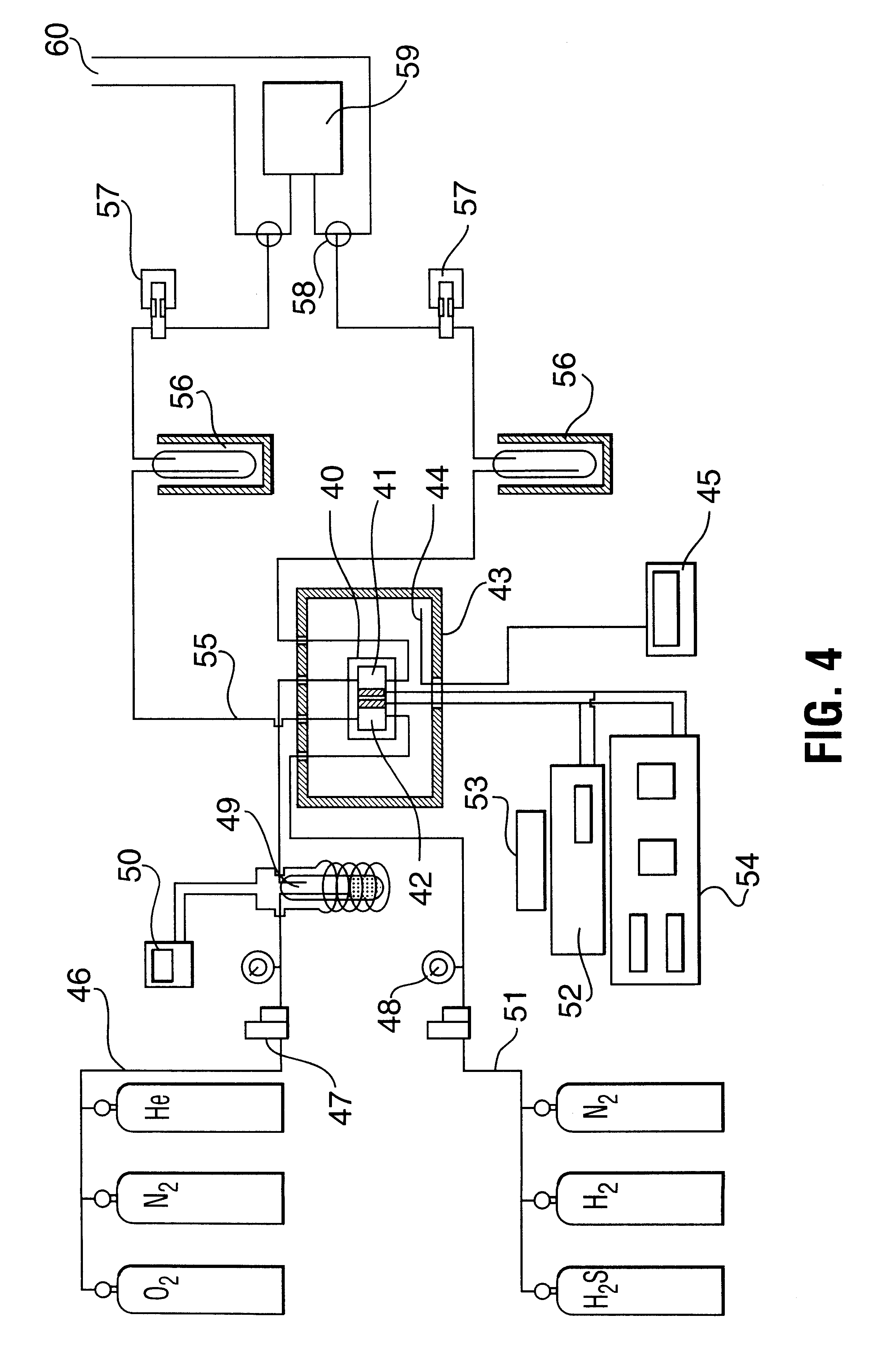
A test was conducted on the electrolysis system of FIG. 4 to determine the dependence of potential and H.sub.2 S conversion as a function of temperature. It was operated as a H.sub.2 S / O.sub.2 fuel cell with a 60.24% MoS.sub.2 / C anode catalyst and a 2.41% Pt / C cathode catalyst (P.08 above). The cell was operated at a pressure of 52 psi (0.36 MPa) and at varying temperatures up to 150.degree. C. The results are illustrated in FIG. 5, which clearly shows the favourable effect of operation at high temperatures, curve (a) showing conversion and (b) showing potential.

example 3

The relationship of H.sub.2 S conversion to anode compartment feed gas flow rate was studied on the system of FIG. 4 at operating as a H.sub.2 S / O.sub.2 fuel cell at conditions of 145.degree. C. and 52 psig (0.36 MPa). For this test, a 9.88% Pd / C anode 2.05% Pt / C catalyst and cathode catalyst combination (P.14) of Table 1 was used. The tests were carried out at flow rates of 4 cm / min, 9 cm.sup.3 / min and 16 cm.sup.3 / min and the results obtained are shown in FIG. 6, with curve (a) being 4 cm.sup.3 / min, (b) 9 cm.sup.3 / min and (c) 16 cm.sup.3 / min.

example 4

In order to determine the stainable operability of the H.sub.2 S / O.sub.2 fuel cell, tests were conducted on the system of FIG. 4 over an extended period while measuring the potential as a function of resistance in the external circuit. The 7.83% Pd / C anode and 2.55% Pt / C cathode catalyst combination (P.03) of Table 1 was used and the fuel cell was operated at a temperature of 125.degree. C. and a pressure 40 psig (0.275 MPa) . The results are shown in FIG. 7 with the curve (a) being for fresh catalyst and curve (b) after 36 hours in operation. The results clearly demonstrate the reliability of the high temperature, high pressure operation of this system.


PUM

PropertyMeasurementUnit
Temperatureaaaaaaaaaa
Pressureaaaaaaaaaa
Pressureaaaaaaaaaa

Abstract

The invention relates to a process for gas phase electrochemical oxidation of H2S to sulfur and water or steam using an electrolysis cell having an anode chamber on one side of a solid proton conducting membrane and a cathode chamber on the other side of the membrane. The process comprises the steps of passing H2S-containing gas through the anode chamber to contact a catalytic anode, where it reacts to produce elemental sulfur, protons and electrons. The protons pass through the membrane from the anode chamber to the cathode chamber. An oxygen-containing gas is passed through the cathode chamber to contact the catalytic cathode, where it reacts with protons and electrons to produce water or steam. During the process, both the anode chamber and cathode chamber are maintained at a temperature of at least 120° C. and an elevated pressure sufficient to keep the membrane moist. Sulfur is obtained in liquid or vapor form and is removed from the anode chamber while water or steam is removed from the cathode chamber. An electric current can be withdrawn from the anode and cathode. The cell can also be operated in the electrolysis mode to produce sulfur and hydrogen.

Description

This invention relates to electrochemical H.sub.2 S spontaneous conversion to sulfur and water with the concurrent production of electrical energy or to sulfur and hydrogen.DESCRIPTION OF THE PRIOR ARTHydrogen sulfide (H.sub.2 S) is a corrosive and extremely toxic gas that is present in natural gas wells at concentrations ranging from a few ppm to 50% or even higher. Hydrodesulfurization of heavy oil and bitumen and coal gasification also produce gas streams containing hydrogen sulfide as an undesirable by-product. At present the approach to removal of H.sub.2 S has been to destroy it by oxidation to steam and sulfur, and not to utilize H.sub.2 S as a hydrogen resource.A number of processes are available for the removal of H.sub.2 S from natural gas and process gas streams, and for converting it into useful or at least harmless products. Most of these methods are multistage processes that begin with chemical or physical absorption of H.sub.2 S. In practice, H.sub.2 S is usually remo...

Claims


Application Information

Patent Timeline
IPC IPC(8): C25B5/00C25B1/00H01M8/06H01M8/12H01M8/22H01M4/90H01M4/92C01B17/04H01M8/04H01M8/10
CPCC25B1/00C25B5/00H01M8/06H01M8/12H01M8/22Y02E60/521Y02E60/525Y02E60/566Y02E60/50
Inventor DONINI, JOHN C.CHUANG, KARL T.SLAVOV, STEFAN V.SANGER, ALAN R.STANIC, VESNA
Owner ETHYL TECH
Why Eureka
Try Eureka