Joint for pre-cast concrete twin-leaf arch sections

a technology of precast concrete and twin-leaf arch sections, which is applied in the direction of sewer pipelines, bridges, building repairs, etc., can solve the problems of time-consuming and laborious to properly orient the two arch sections with respect to each other, and achieve the effect of efficient and accurate formation

Inactive Publication Date: 2001-06-12
CONTECH ENGINEERED SOLUTIONS
View PDF26 Cites 73 Cited by
  • Summary
  • Abstract
  • Description
  • Claims
  • Application Information

AI Technical Summary

Benefits of technology

It is a main object of the present invention to provide a joint for precast concrete twin-leaf arch sections which is efficiently and accurately formed.
The self-aligning feature of the present invention provides a joint for precast concrete twin-leaf arch sections which is efficiently and accurately formed. Once formed, the joint securely maintains the relative orientation between the arch sections. The joint embodying the present invention can be accurately and efficiently formed in situations where scaffolding cannot be used.

Problems solved by technology

These large structures need to be built from two or more arch segments due to transporting size and weight restrictions.
The use of a central scaffolding is then not possible and two cranes are used for the installation.
If used with the method of FIG. 1, it is time consuming to properly orient the two arch sections with respect to each other.
The joint is not locked when in abutting contact, and often, the uncontrolled transmission of the abutting force leads to spalling of the concrete.

Method used


Image

  • Joint for pre-cast concrete twin-leaf arch sections
  • Joint for pre-cast concrete twin-leaf arch sections
  • Joint for pre-cast concrete twin-leaf arch sections

Examples


Embodiment Construction

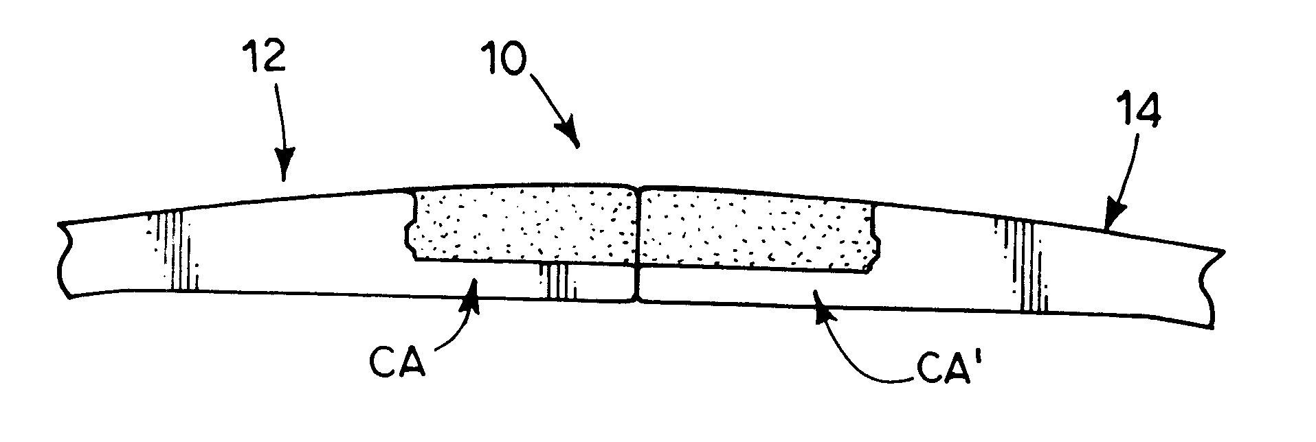
Shown in FIG. 6 is a joint 10 which mechanically locks one arch section 12 to another arch section 14 of a pre-cast concrete twin-leaf arch. The mechanical lock 10 efficiently and effectively joins section 12 to section 14 at initial abutting contact between the crown areas CA and CA' of these two sections and then maintains that locked connection while the remainder of the joint is formed.

Arch section 12 is shown in FIG. 7A and includes a main body 18 having a top surface 20 and a bottom surface 22. An end portion 24 includes a shoulder 26 connecting top surface 20 to a joint top surface 30 with thickness 32 between surfaces 22 and 30 being less than thickness 34 between surfaces 20 and 22 whereby a boxed-out portion, or step 36 is defined by surfaces 20 and 22 and shoulder 26. A central portion 38 extends from shoulder 26 to end 40 of arch section 12. A face 42 on portion 38 is co-planar with face 44 of end 40 and has a depression 46 defined therein to extend from face 42 towards ...


PUM


Abstract

A joint for pre-cast concrete twin-leaf arch sections is self-aligning when the two arch sections are initially brought into abutting contact with each other. The joint provides a rigid connection between the twin units and is achieved on site by means of re-inforced cast-in-place concrete. Reinforcement splices for the connection are lap splices, and the joint allows pouring the cast-in-place concrete without the need of formwork. For load distributing purposes, a continuous connection of individual arch rings in the longitudinal direction at the arch crown is possible. An initial abutting contact between the twin units is provided by the joint of the present invention. The contact provided by the joint of the present invention is self-aligning, locking, allows the controlled transmission of the abutting force and allows for a temporary connection. The joint includes mechanical elements for aligning and locking the two arch sections together. The mechanical elements include, in the preferred embodiment, a projection on one arch section and a depression on the other arch section. Cast-in-place concrete is placed in boxed-out, or step, sections located adjacent to the mechanical elements and completes the joint.

Description

The present invention relates to the general art of large pre-cast concrete arch structures, and to the particular field of joints for large pre-cast concrete arch structures.Large span pre-cast concrete arch structures are often used in road building and the like. As used herein, the term "large arch structure" will mean an arch structure large enough for pedestrian or vehicular passageways, parking or large enough to support vehicle traffic over a roadway or a waterway as opposed to conduits and the like which enclose cables or drainage. These large structures need to be built from two or more arch segments due to transporting size and weight restrictions. Such arch segments are connected on site. A structure formed of twin-leaf arch sections is shown in FIG. 3.Quite often, a rigid connection of precast concrete elements is made from reinforced cast-in-place concrete. The simplest and most commonly used joint for reinforcing steel is a lap splice. The present invention uses reinfo...

Claims


Application Information

Patent Timeline
Patent Type & Authority Patents(United States)
IPC IPC(8): E02D29/045E04B1/32
CPCE02D29/045E04B1/3205E04B2001/3217E04B2001/3264E04B2001/3276
Inventor BERNINI, JOE
Owner CONTECH ENGINEERED SOLUTIONS
Why Eureka
Try Eureka