Safety incinerator for rubbish in volume and flammable waste

a technology of incinerators and waste, which is applied in the direction of combustion process, furnace components, lighting and heating apparatus, etc., and can solve the problems of high operational expenses

Inactive Publication Date: 2001-06-12
YANG DAE YOUN
View PDF10 Cites 7 Cited by
  • Summary
  • Abstract
  • Description
  • Claims
  • Application Information

AI Technical Summary

Problems solved by technology

However, there are problems with the electricity and the petroleum as the combustion power of incinerators created high operational expenses.

Method used


Image

  • Safety incinerator for rubbish in volume and flammable waste
  • Safety incinerator for rubbish in volume and flammable waste
  • Safety incinerator for rubbish in volume and flammable waste

Examples


Embodiment Construction

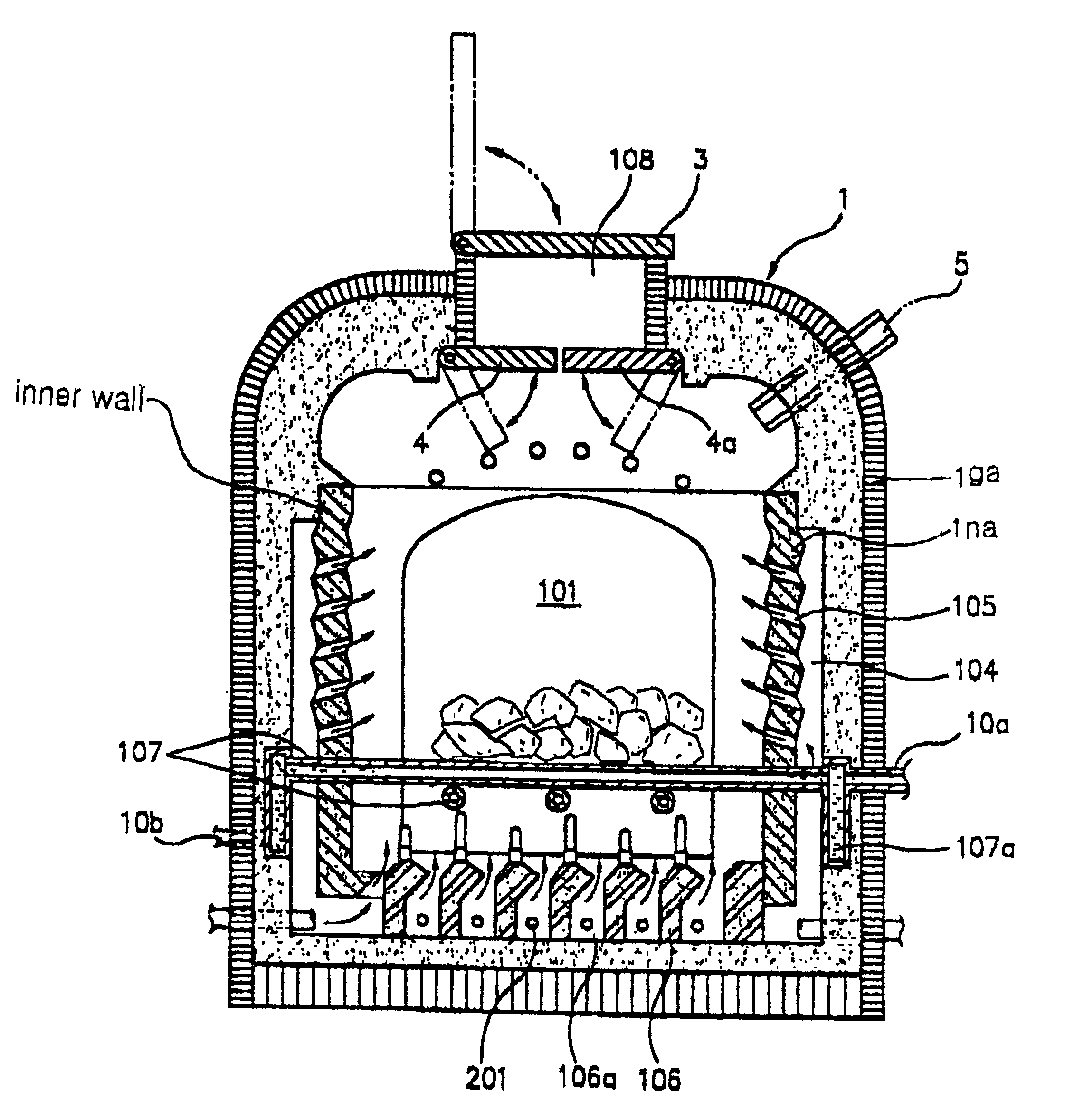
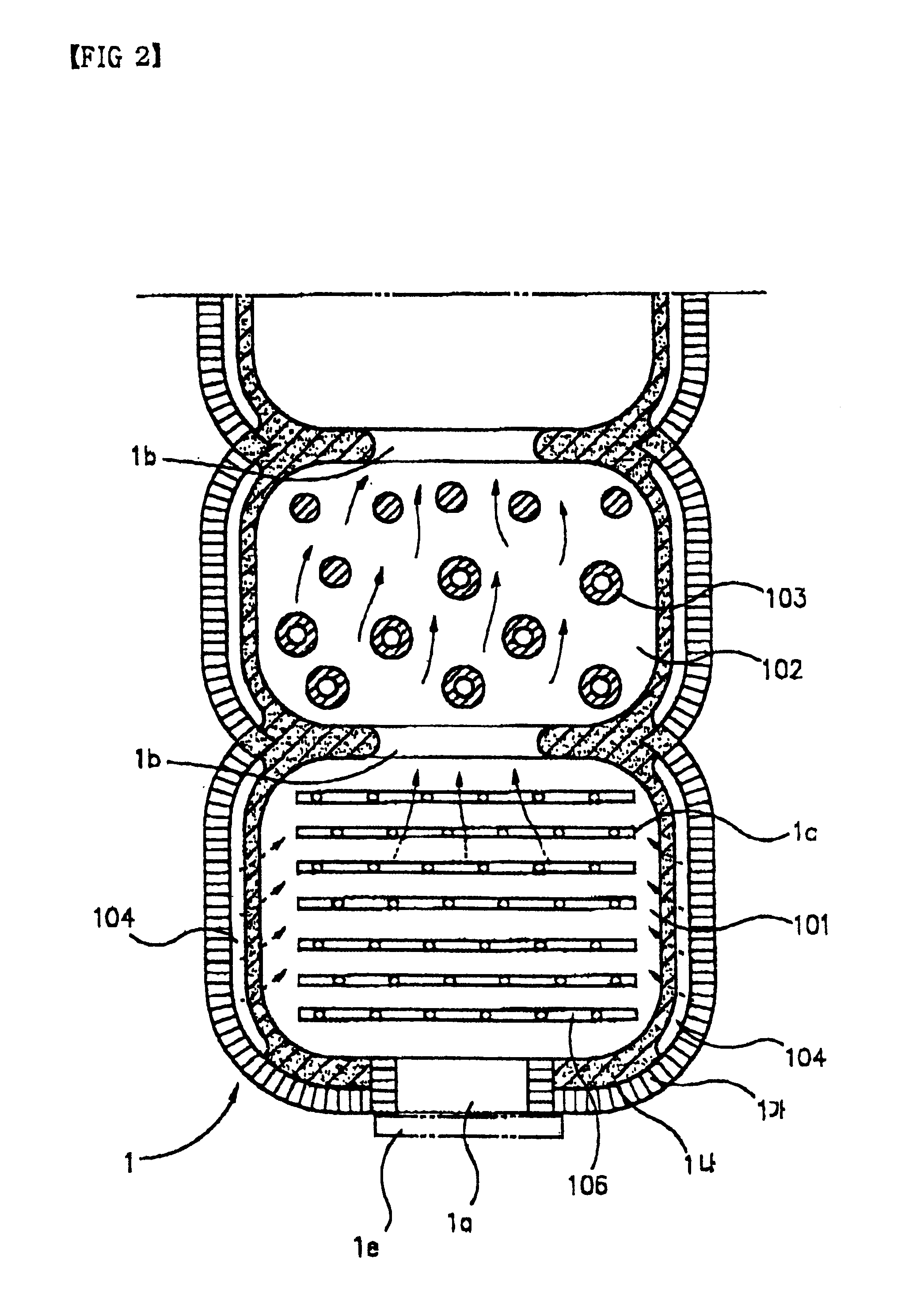
The present invention provides an incinerator 1 in a tunnel shape which is formed by connecting the combustion chamber 101 in a dome shape and the auxiliary combustion chamber 102 alternately, wherein the inside wall 1 na of the combustion chamber 101 is made of ceramic material mixed with natural minerals such as loess, plate-powder and mica, and the outside wall 1 ga thereof is made of heat insulating material so that the heat resistance and the thermo-keeping are high. The infrared rays are radiated therefrom and the high temperature atmosphere is kept. The air supply chamber is formed between the outside wall and the inside wall of the combustion chamber 101. The air supply chamber is connected to the supply pipe 201 and the outside air supply device 2. A large number of air vents 105 are formed along the inside wall 1 na to force the combustion air to the combustion chamber 101 from the air supply chamber 104. The air cooled grate 106 and the water cooled grate 107 are installe...


PUM


Abstract

This invention is a mass incinerator for burning various rubbishes (life rubbishes, industry wastes, hospital rubbishes and like) and flammable wastes (hospital wastes, poison material and like) under high temperature atmosphere. In particularly; to an incinerator in which the combustion chambers 101 constructed in a dome form and the auxiliar combustion chambers 102 are connected alternately to form a tunnel shape. An air supply chamber 104 is formed between the outside wall and the inside wall of the combustion chamber 101. The materials being burned are inputted through the double hinged gate so that the soot or the dust is not scattered outward. The input during the combustion process is possible to improve the treating whereby rubbishes or wastes are completely burnt to prevent the environmental pollutant such as heavy metal material or dioxin as well as soot from discharging. Also, the hot water produced by the heat generated from the combustion process is supplied for agriculture, industry and home and used for generating electricity.

Description

1. Field of the InventionThis invention relates to a mass incinerator which can incinerate continuously various rubbish (life rubbish, industrial wastes, hospital rubbish and the like) and flammable wastes (hospital wastes, poison and the like) at high temperature, particularly, to an incinerator in which several combustion chambers constructed in a dome form such as a pottery kiln are connected in a tunnel shape to form the incinerator. Each combustion chamber is made of ceramic material to show the high thermo-keeping and the excellent emission function of the infrared ray. It has an air supply device and an auxiliary fuel feeding device to incinerate continuously rubbish or wastes for a long time. Thus, any pollutant is not discharged and the heat occurring during the combustion process makes hot water.2. Description of the Prior ArtAccording to the development of the industry, the amount of rubbish and wastes has been increased day by day. The kinds thereof has been also varied ...

Claims


Application Information

Patent Timeline
Patent Type & Authority Patents(United States)
IPC IPC(8): F23G5/08F23H3/00F23G5/16F23H3/02F23G5/12F23M5/00
CPCF23G5/12F23G5/16F23H3/02F23M5/00F23G2202/103F23M2900/05004
Inventor YANG, DAE YOUN
Owner YANG DAE YOUN
Why Eureka
Try Eureka