Wide band antenna means incorporating a radiating structure having a band form

Inactive Publication Date: 2001-06-12
ALLGON
View PDF7 Cites 29 Cited by
  • Summary
  • Abstract
  • Description
  • Claims
  • Application Information

AI Technical Summary

Problems solved by technology

This antenna structure demands a quite large amount of space, which makes it unpractical for use in small hand-portable telephones or where there is a need for small and efficient antenna means.
Further its manufacture is rather complicated.
An antenna of this kind has the disadvantage that, with the top capacitance, it is difficult to achieve a desired electrical/physical length

Method used


Image

  • Wide band antenna means incorporating a radiating structure having a band form
  • Wide band antenna means incorporating a radiating structure having a band form
  • Wide band antenna means incorporating a radiating structure having a band form

Examples


second embodiment

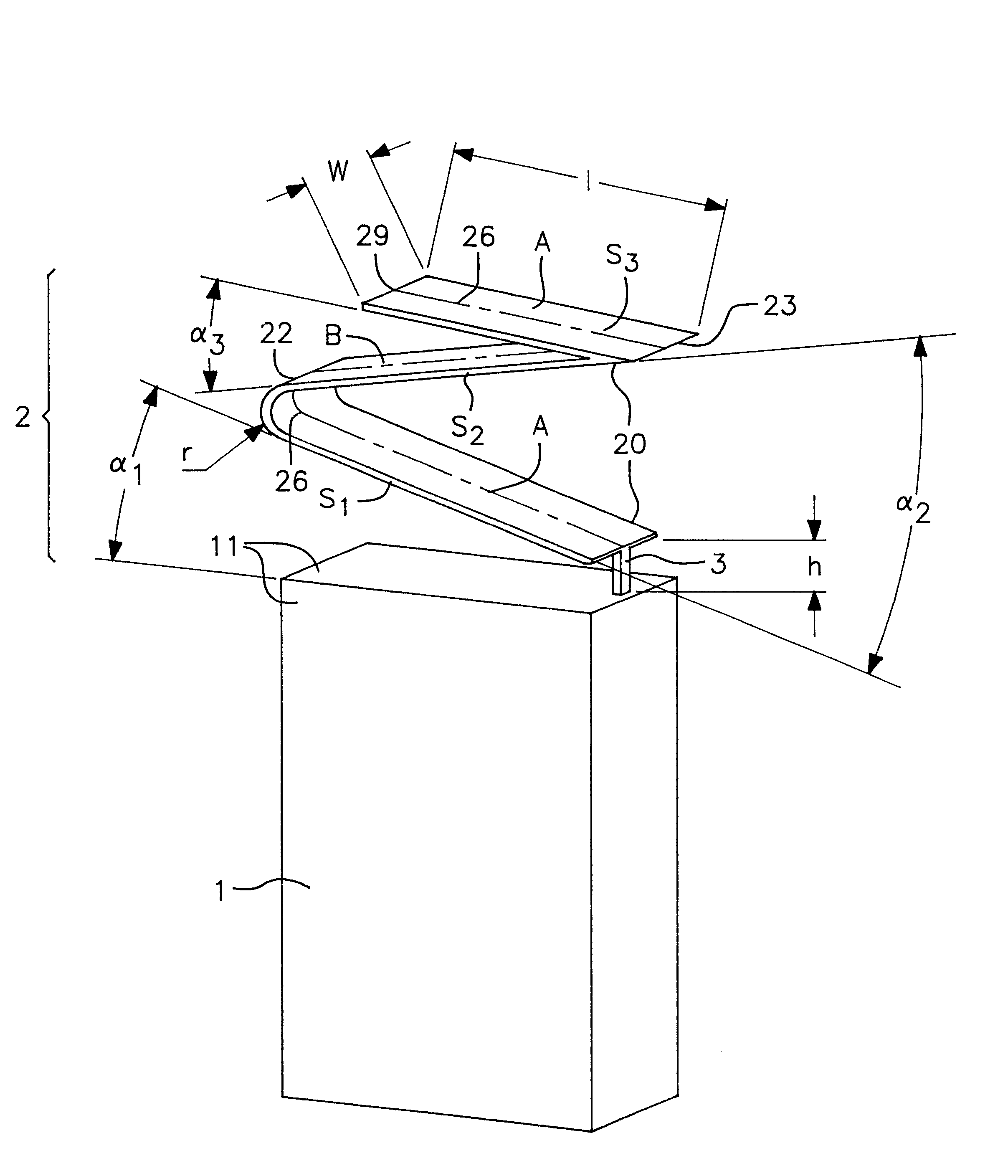
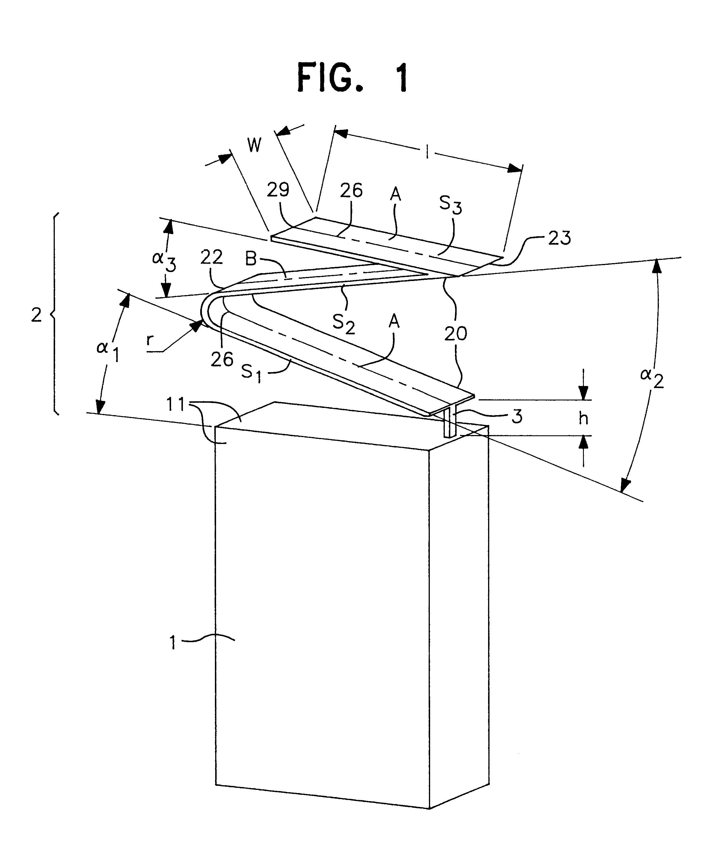
FIG. 2 shows diagrammatically a hand portable cellular telephone 1, provided with an antenna means 2 according to the invention seen obliquely from below and sideways. This radiating structure 20 includes five sections, and the feed portion 3 is a unitary continuation of the band shaped radiating structure 20. The ground plane can be formed of the part 11 of the housing of the telephone 1 below the radiating structure 20, as in the previous embodiment. Alternatively, it can be formed of a part 12 of the housing of the telephone 1 extending parallel with the radiating structure 20, or both 11 and 12.

third embodiment

FIG. 3 shows diagrammatically a hand portable cellular telephone 1, provided with an antenna means 2 according to the invention, in a side view. From this figure it is seen that the radiating structure 20 has a greater width in the top, at the free end 29, than in the bottom where it is connected to the feed portion 3. This can be made by giving the band shaped radiating structure 20 an increasing width continuously or step by step along its length.

fourth embodiment

FIG. 4 shows diagrammatically a hand portable cellular telephone 1, provided with an antenna means 2 according to the invention, in a side view. In this embodiment, the radiating structure 20 is tilted an angle .gamma. in relation to the ground plane. In this embodiment, the ground plane can be formed of the part 11 or the part 12 of the housing of the telephone 1, or both parts 11 and 12.


PUM


Abstract

An antenna means (2) for transmitting and receiving RF signals, comprising: a ground plane (11) arranged to be connected to ground of the circuitry of a radio communication device and a conductive radiating structure (20) in the form of a band. The radiating structure has in a first end a feed portion (21) arranged to be coupled to circuitry of a radio communication device. The radiating structure has a second end which is a free end (29). The band has a first (A) and a second (B) surface, and is divided by bent portions into a number of sections Sn along its length. The band is bent or folded so that the first surface (A) of a first section S1 faces the first surface (A) of a second section S2, being adjacent to the first section S1, and the second surface (B) of a section Sm faces the second surface (B) of a consecutive section Sm+1, whereby a compact antenna means which can operate within a wide frequency band is achieved.

Description

FIELD AND BACKGROUND OF THE INVENTIONThe invention relates to an antenna means for transmitting and receiving RF signals having a radiating structure with a band shape. Specifically, it relates to an antenna device for a mobile radio communication device, e.g., a hand-portable telephone or a car radio antenna, which is capable of both transmitting and receiving on multiple separate frequency bands. This would increase the probability of the telephone being operable for communication in a site where service is available within more than one band. Such a telephone may be a terminal in, e.g., a GSM, PCN, DECT, AMPS, PCS, and / or JDC cellular telephone system, possibly having an additional pager function or other radio facilities. The frequencies included in the multiple bands of the invention do not need to have any fixed relationship to one another and may thus have arbitrary separations.The invention also relates to an antenna means which is compact, and requires a small space. For mo...

Claims


Application Information

Patent Timeline
IPC IPC(8): H01Q9/44H01Q1/36H01Q5/00H01Q1/08H01Q9/42H01Q9/04H01Q1/24H01Q1/22H01Q5/357H01Q5/371
CPCH01Q1/08H01Q1/242H01Q1/36H01Q5/371H01Q9/44H01Q5/357H01Q9/42H01Q1/24
Inventor KURZ, HANS-PETERHELLGREN, MATTIASYIDONG HU, ANNIKA
Owner ALLGON
Why Eureka
Try Eureka