Coupling alignment warning system

a warning system and coupling technology, applied in navigation instruments instruments for comonautical navigation, etc., can solve the problems of high or low coupling, damage to the truck, trailer and/or the interlocking apparatus, and the driver often experiences difficulty in aligning the throat of the hitch plate with the king pin

Inactive Publication Date: 2001-06-26
SW PELHAM FUND LP +3
View PDF16 Cites 49 Cited by
  • Summary
  • Abstract
  • Description
  • Claims
  • Application Information

AI Technical Summary

Problems solved by technology

Such practice often leads to high or low coupling and, possibly, lateral misalignment between the truck and the trailer, which can result in damage to the truck, trailer and / or the interlocking apparatus.
When backing up the towing unit, the driver often experiences difficulty in aligning the throat of the hitch plate with the king pin.
For instance, the height of the king pin relative to the throat may be such that proper mating between the two will not be achieved, even though the two may be laterally aligned.
In these instances, the front lower edge of the trailer may crash into the fifth wheel hitch plate (trailer and king pin too low) or the cab of the truck may crash into the body of the trailer (trailer and king pin too high).
Alternatively, even though the king pin and fifth wheel hitch may appear coupled, if the king pin is not seated properly in the locking mechanism a "high couple" may result leading to an unsafe and potentially dangerous condition.
On the other hand, even if the two components are at the proper engaging height relative to one another, the throat and the king pin may be laterally misaligned.
In either case, positive coupling is not achieved, and the interlocking apparatus and / or the truck / trailer may be damaged or unsafe.
Further, the problems attendant with this "guesswork" are exacerbated by the fact that the driver will often be faced with zero or low visibility conditions (night, severe weather, sleeper cab configurations, etc.)
Notably, known systems are targeted toward the "ball and hitch" coupling market and are not easily adaptable to the heavy trucking industry.
As such, these systems are limited in range (typically less than 20 feet) and require separate sets of infrared sensors on the towing and towed units, respectively, to indicate the lateral offset and vertical alignment.
Clearly, these systems are limited in their application, inconvenient and relatively expensive.
In sum, current commercial truck / trailer coupling is performed relatively "blind" because direct observation of the king pin relative to the fifth wheel lock often is not possible.
Further, systems such as air-bag suspensions lead to variable trailer and truck height, making positive coupling even more difficult.
However, such practice often, as described above, leads to missed or incomplete or "hard coupling."
These problems, and the damage often associated therewith, are worsened when the driver is faced with low visibility conditions due to cab design, darkness, weather, etc.

Method used


Image

  • Coupling alignment warning system
  • Coupling alignment warning system
  • Coupling alignment warning system

Examples


Embodiment Construction

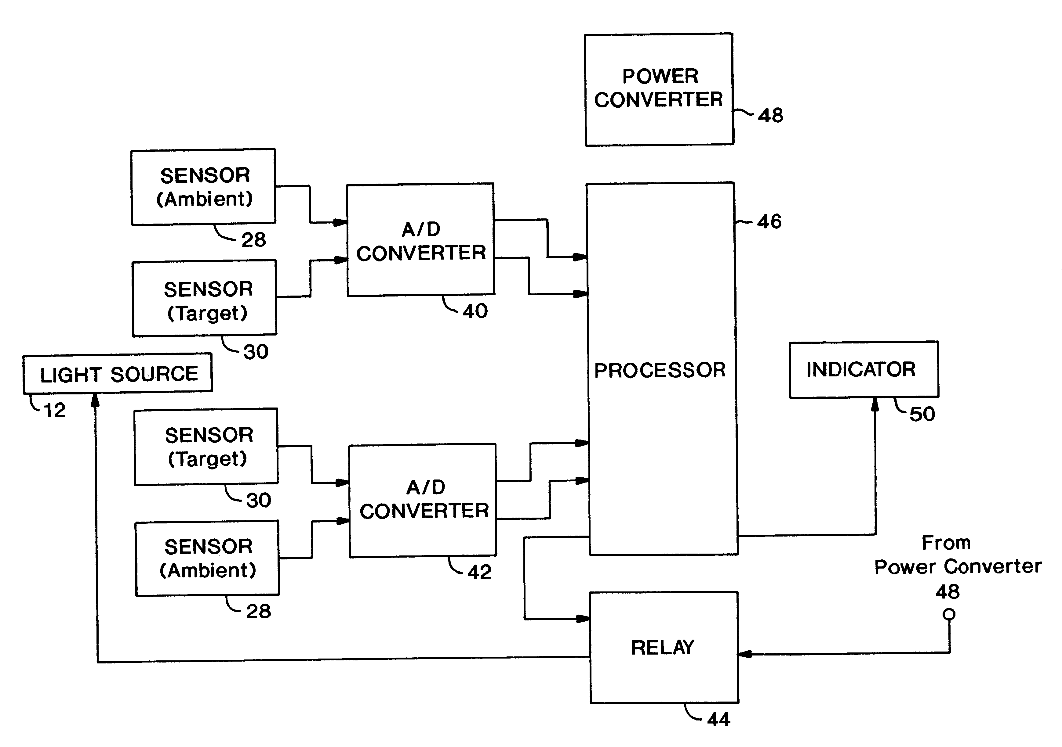
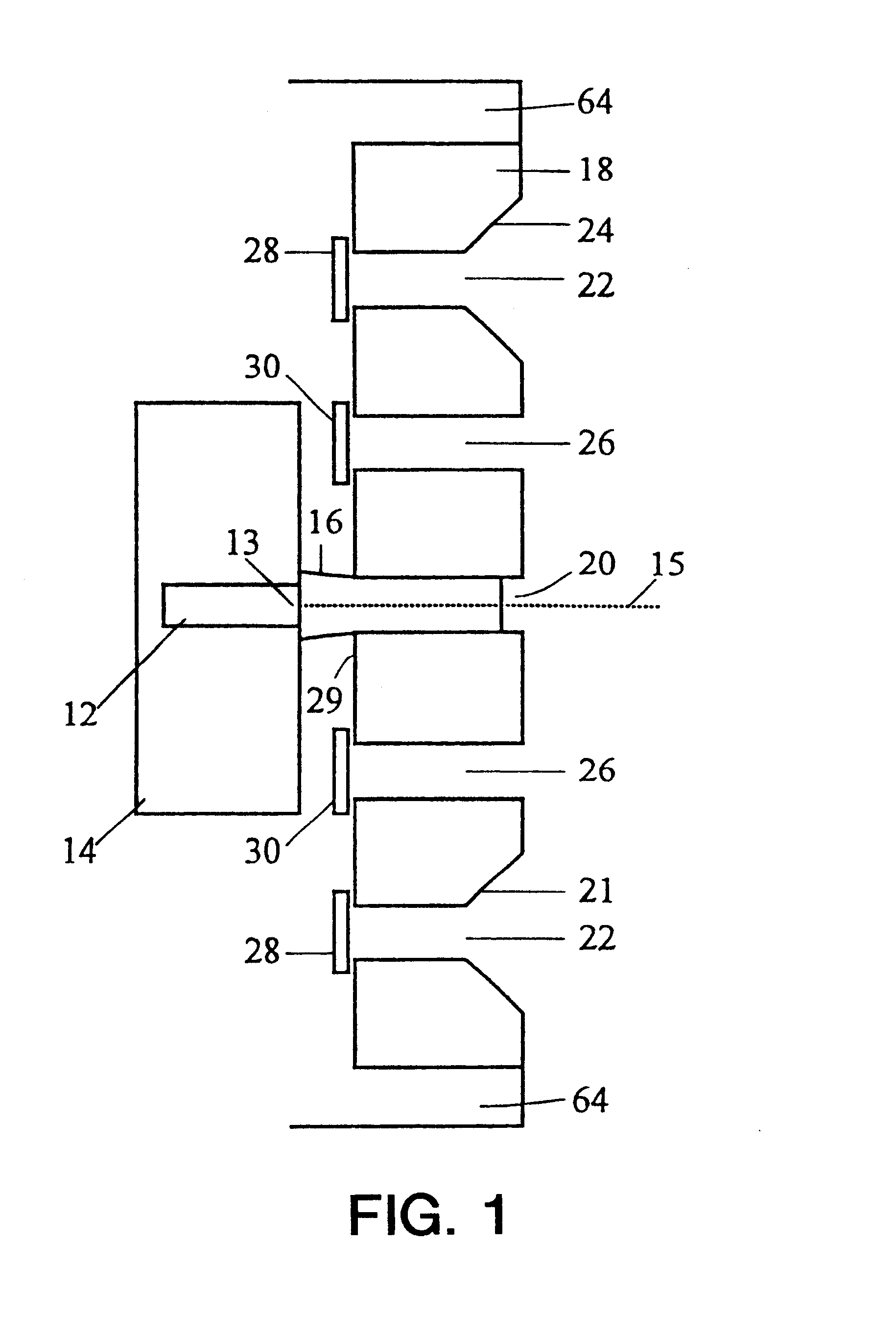
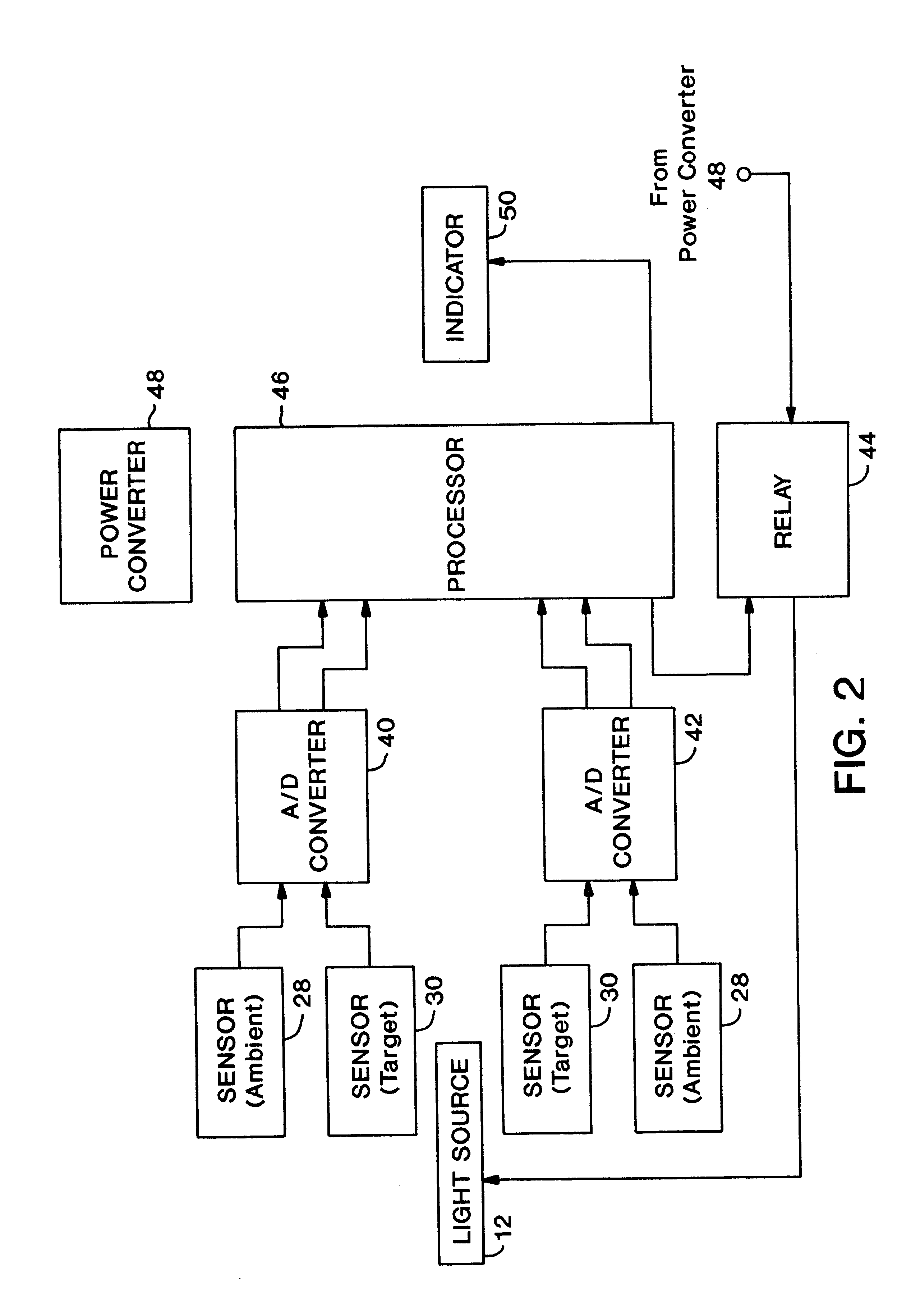
Referring in more detail to the drawings, FIG. 1 shows the transmitter / receiver components of the coupling alignment warning system (CAWS) 10 for aligning a towing unit with a towed unit by detecting ambient and reflected laser light in the system. In particular, the transmitter includes a laser light source 12 (preferably, a laser diode) that is mounted in an adjustable support 14 that is, in turn, attached to the interior of a rugged enclosure 64. In the preferred embodiment, rugged enclosure 64 is mounted to the towing unit during initial installation as described in more detail below (FIG. 3). The receiving components of the system, which are also shown in FIG. 1, include a spatial filter 18 and a series of sensors 28, 30. Spatial filter 18 has a series of optical tunnels 22, 26 that limit the amount of light that may reach both ambient sensors 28 and target sensors 30, that are positioned adjacent thereto, by restricting the angles at which light may impinge upon sensors 28, 30...


PUM


Abstract

The coupling alignment warning system (CAWS) of the instant invention is designed to provide the driver of a towing unit, e.g., a commercial truck, with visual and/or audible cues that indicate whether the towing unit is aligned relative to a towed unit for proper engagement of the coupling components mounted thereon, including a fifth wheel hitch on the towing unit and a king pin on the trailer. The CAWS combines a laser light source and a series of sensors with a reflective target to provide alignment information to the user. In particular, the system combines a low-power laser diode mounted on the towing unit with a retro-reflective target that is attached, preferably temporarily, on the towed unit. The target will continuously return positive coupling alignment information back to the sensors as long as laser light impinges upon the target, i.e., as long as target acquisition is maintained. The sensors transmit detection signals to a processing unit that includes a microprocessor and relay. The microprocessor is programmed to calculate a threshold level of light that is based on sensed ambient light signals. In operation, the microprocessor decodes the detected light and determines whether the detected light level reaches the threshold level of light. If so, the CAWS indicates to the user that target acquisition has been achieved, and thus, that the towing unit is aligned with the towed unit for positive coupling. The microprocessor also controls the relay, thus controlling the delivery of power to the laser light source so that the system can continually compute an updated threshold level of light based on the ambient light in the surrounding operating environment. As a result, the system minimizes the chance of triggering on false light signals, notwithstanding varying ambient light conditions. The CAWS is particularly useful in zero or low visibility conditions because it can be used in conjunction with mirrors and external reference points to provide reliable position information to the user.

Description

1. Field of the InventionThe present invention relates to systems for aligning a towing unit with a towed unit, e.g., a trailer. In particular, the instant invention is adapted to assist the driver of the towing unit with aligning the fifth wheel hitch of a commercial truck and the king pin of a trailer to achieve positive coupling between the two, especially in zero or low visibility conditions.2. Discussion of Related ArtTo couple a vehicle, such as a commercial truck, to a trailer, the driver must continually estimate the position of the vehicle relative to the trailer while maneuvering the vehicle into alignment with the trailer. In practice, this may involve exiting the truck to determine the position of the truck relative to the trailer and then re-entering the truck to maneuver it into alignment. In addition, the driver utilizes his rearview side mirrors to approximate the lateral alignment between the truck and trailer, while vertical alignment is often judged only by "feel,...

Claims


Application Information

Patent Timeline
Patent Type & Authority Patents(United States)
IPC IPC(8): B62D53/12B62D53/00B60D1/01G01B11/00B62D53/08
CPCB62D53/12
Inventor DUPAY, STEVEN C.SCHUTT, RANDY L.
Owner SW PELHAM FUND LP
Why Eureka
Try Eureka