Retina cell microscopic imaging system with optical system for eliminating false light

A retinal cell and optical system technology, applied in the field of retinal cell microscopic imaging system, achieves the effect of simple structure, obvious effect and improved clarity

Inactive Publication Date: 2008-10-29
江阴龙跃信息科技有限公司 +1
View PDF4 Cites 2 Cited by
  • Summary
  • Abstract
  • Description
  • Claims
  • Application Information

AI Technical Summary

Problems solved by technology

In actual use, the circular aperture diaphragm can intercept the stray light outside the circular aperture, but the stray light focused or projected in the circular

Method used


Image

  • Retina cell microscopic imaging system with optical system for eliminating false light

Examples


Embodiment

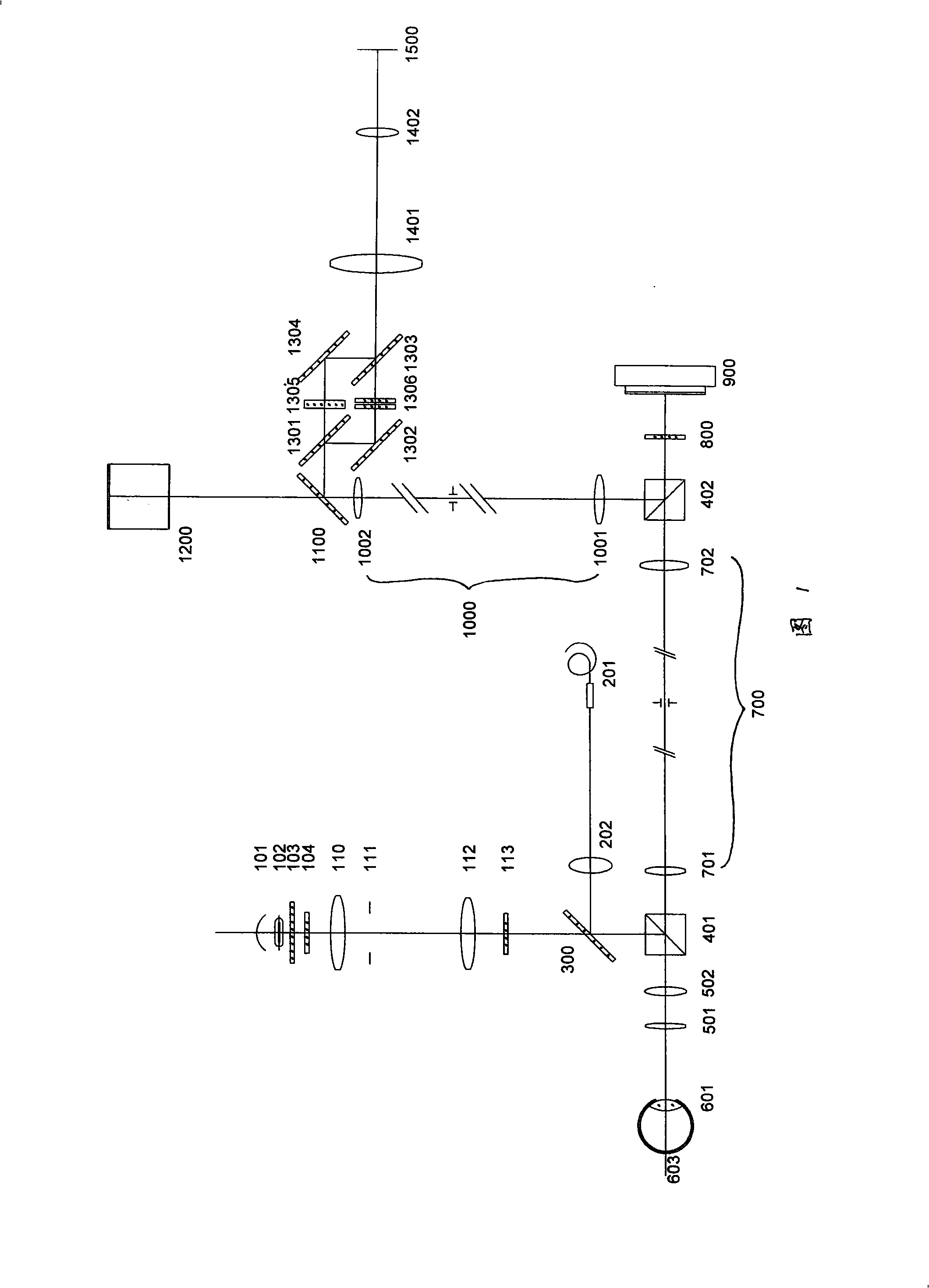
[0015] Embodiment: as shown in Fig. 1, a kind of retinal cell micro-imaging system with stray light optical system, it includes illumination system, micro-imaging optical system, in the optical path between human eye 601 and micro-imaging optical system , a wavefront corrector 900 is provided.

[0016] In the optical path between the human eye 601 and the wavefront corrector 900, a first polarizing beam splitting prism PBS 401 for eliminating stray light is arranged.

[0017] In the stray light elimination optical system of the retinal cell microscopic imaging system, after the parallel light beam from the light source enters the first polarizing beam splitting prism PBS 401, the P light vibrating along the direction of the paper plane passes through, and the S light vibrating perpendicular to the paper plane direction is reflected and transmitted toward the human eye 601. Since the reflection of polarized light by human eye tissues such as lens, cornea, and other surfaces th...


PUM


Abstract

The present invention discloses a retina cell microscopic imaging system with a stray light eliminating optical system, which comprises an illuminating system and a microscopic imaging optical system. The inside of an optical path between the illuminating system and a human eye (601) is provided with a first polarization beam splitter prism PBS (401) which eliminates the stray light, and the first polarization beam splitter prism PBS (401) is also arranged inside the optical path between the human eye (601) and the microscopic imaging optical system. The retina cell microscopic imaging system of the present invention provides a retina cell microscopic imaging system with the stray light eliminating optical system, which uses a new stray light eliminating technology, has simple structure and can effectively improve the retina imaging definition.

Description

technical field [0001] The invention relates to a retinal cell microscopic imaging system, in particular to a retinal cell microscopic imaging system with an optical system for eliminating stray light. Background technique [0002] In the existing retinal cell microscopic imaging system, the involved stray light elimination system generally adopts the confocal diaphragm technology commonly used in optical systems, and the adopted diaphragm is a round through hole. For example, the stray light elimination technology mentioned in CN99115051.1, CN99115052.X, CN99115053.8 and CN99115054.6 patents applied by the Institute of Optoelectronic Technology, Chinese Academy of Sciences. In actual use, the circular aperture diaphragm can intercept the stray light outside the circular aperture, but the stray light focused or projected in the circular aperture can still pass through the aperture and cannot be intercepted, especially the Paraxial stray light is difficult to intercept throu...

Claims


Application Information

Patent Timeline
IPC IPC(8): A61B3/13
Inventor 周明宝张运海任建伟
Owner 江阴龙跃信息科技有限公司
Why Eureka
Try Eureka