Multibeam antenna having auxiliary antenna elements

a technology of antenna elements and antennas, applied in the direction of antennas, antenna details, antenna adaptation in movable bodies, etc., can solve the problems of difficult arbitrarily increasing the antenna gain, unavoidable formation of large sidelobes, etc., and achieve the effect of improving the directivity of beams and improving the antenna gain

Inactive Publication Date: 2001-06-26
DENSO CORP
View PDF6 Cites 86 Cited by
  • Summary
  • Abstract
  • Description
  • Claims
  • Application Information

AI Technical Summary

Benefits of technology

According to the present invention, sidelobes of the multiple beams formed by the antenna array are reduced, and the beam directivity is improved. Moreover, the antenna gain can be improved by properly arranging the antenna elements and properly setting the power distribution among the antenna elements.

Problems solved by technology

Accordingly, the beam shapes formed by the antenna are solely determined depending on the distance among antenna elements, and formation of large sidelobes is unavoidable, as generally known.
Therefore, it is difficult to arbitrarily increase the antenna gain.

Method used


Image

  • Multibeam antenna having auxiliary antenna elements
  • Multibeam antenna having auxiliary antenna elements
  • Multibeam antenna having auxiliary antenna elements

Examples


first embodiment

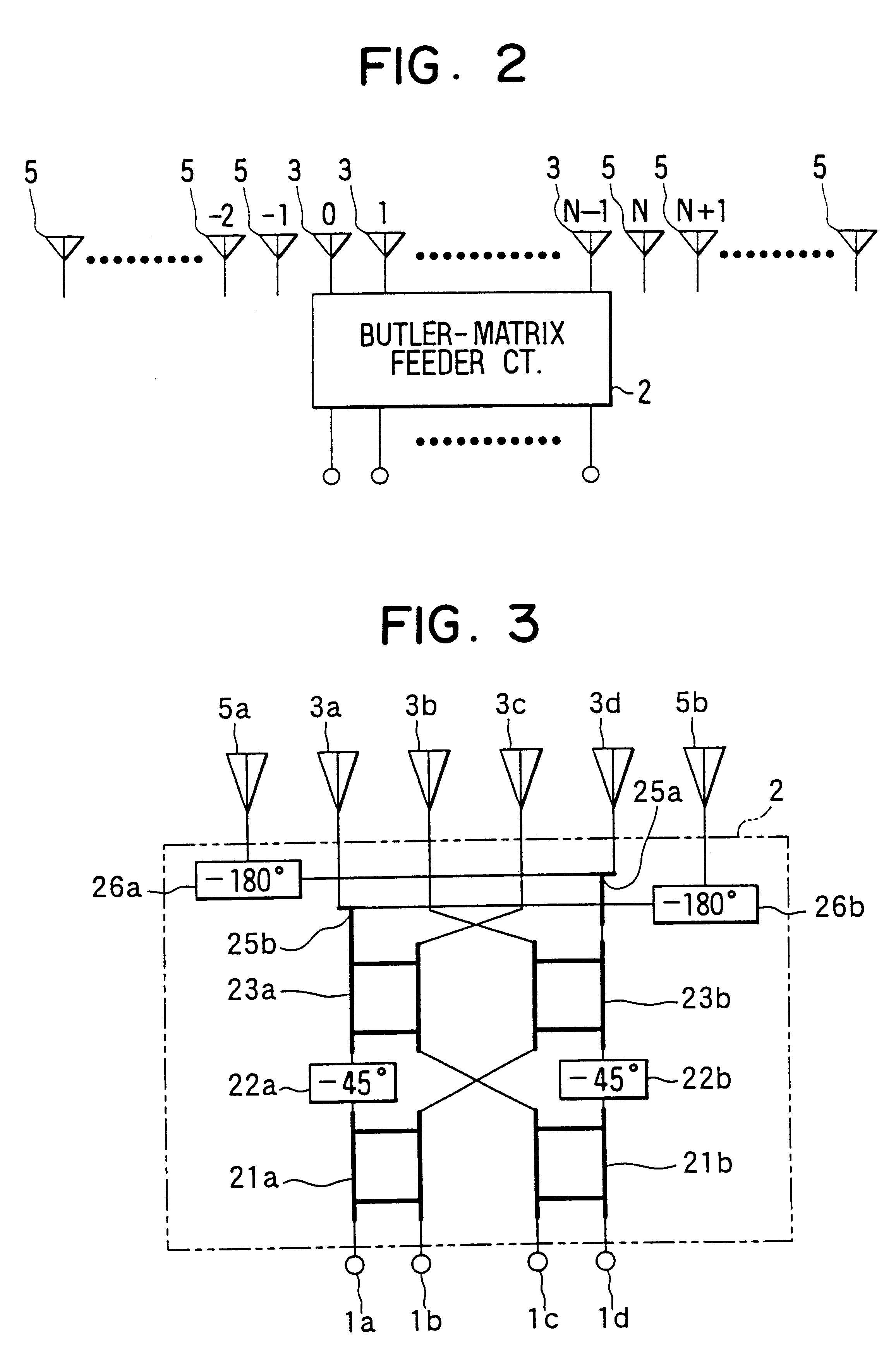
The radiation pattern of the multibeam antenna shown in FIG. 3 is plotted in the graph of FIG. 4, in which relative power in dB is plotted on the ordinate versus the beam angle on the abscissa. This graph is obtained by simulation under the conditions that all the antenna elements including the auxiliary antenna elements are placed with an equal interval of 0.5 wavelength and that the antenna power is distributed to each antenna element with ratios 0.1, 0.9, 1.0, 1.0, 0.9, and 0.1 (from the left to the right in FIG. 3). The radiation pattern of the conventional multibeam antenna shown in FIG. 21 reveals that there are sidelobes of -8 dB level. In contrast, it is seen in FIG. 4 that the sidelobe level of the first embodiment is reduced to a level of -15 dB. This means that the sidelobe level can be reduced by placing auxiliary antenna elements at both sides of the main antenna elements and by distributing low power to auxiliary antenna elements.

FIG. 5 shows the radiation pattern of t...

second embodiment

the present invention will be described in reference to FIGS. 10, 11 and 12. When the phase difference between antenna elements becomes large, the antenna gain decreases. To cope with this problem, power is fed to the auxiliary antenna elements 5a, 5b from the input port side of the feeder circuit 2 as shown in FIG. 10. Power dividers 29a and 29b are disposed at the input ports 1b and 1c, respectively, and the power, the phase of which is adjusted by constant-phase shifters 30a, 30b, is distributed to the auxiliary antenna elements 5a, 5b. When the power is input from the input ports 1b or 1c and the phase difference becomes large, an antenna array is constituted by five antenna elements. When power is input from the input ports 1a or 1d, an antenna array is constituted by four antenna elements. Thus, the antenna gain deviation according to the input ports from which the power is input is suppressed. The phase differences .alpha..degree. and .beta..degree. of the power distributed t...

third embodiment

the present invention will be described in reference to FIG. 13. Since the Butler-matrix feeder circuit is structured based on the fast Fourier transform (FFT) theory in digital signal processing, similar beams as in the Butler-matrix antenna can be formed by performing Fourier transform under the digital beam forming (DBF). The third embodiment shown in FIG. 13 is structured based on this concept. Frequency converters 40a-40d are connected to the output port side of the feeder circuit 2, and the outputs from the frequency converters 40a-40d are converted into digital signals by A / D converters 41a-41d connected to the frequency converters. Then, Fourier transform is performed on the digital signals by a fast Fourier transformer 42. In this manner, the same multiple beams as those in the first embodiment can be formed.

An antenna system as a fourth embodiment of the present invention is shown in FIG. 14. Three Butler-matrix antennas 50, each of which is the same as that of the first e...


PUM


Abstract

A multibeam antenna for forming multiple beams includes an antenna array and a Butler-matrix feeder circuit. The antenna array is composed of 2.sup.n main antenna elements and a group of 2.sup.n or less auxiliary antenna elements placed at either one or both sides of the main antenna elements. Antenna power is supplied to the antenna array from the Butler-matrix feeder circuit and is distributed to all the antenna elements with higher power to the elements located in the middle of the array and lower power to the elements located at sides of the array. Phase of the power supplied to the main antenna elements is shifted by 180-degree, and the phase-shifted power is distributed to predetermined auxiliary antenna elements. Thus, sidelobes associated with antenna beams are reduced and the beam directivity is improved.

Description

CROSS-REFERENCE TO RELATED APPLICATIONThis application is based upon and claims benefit of priority of Japanese Patent Application No. Hei-11-43802 filed on Feb. 22, 1999, the content of which is incorporated herein by reference.BACKGROUND OF THE INVENTION1. Field of the InventionThe present invention relates to a multibeam antenna used in a wireless communication system, more particularly to a multibeam antenna which includes auxiliary antenna elements disposed next to main antenna elements and to an antenna system in which such an antenna is used.2. Description of Related ArtAn antenna for forming multiple beams by supplying power thereto from a Butler-matrix feeder circuit is known hitherto. The Butler-matrix feeder is proposed and described in ELECTRONIC DESIGN, VOL. 9, pp. 170-173, issued April, 1961 under a title "Beam-forming matrix simplifies design of electronically scanned antennas." The Butler-matrix feeder has 2.sup.n input / output ports and composed of hybrid circuits an...

Claims


Application Information

Patent Timeline
Patent Type & Authority Patents(United States)
IPC IPC(8): H01Q25/00H01Q21/08H01Q3/40
CPCH01Q21/08H01Q25/00H01Q3/40H01Q21/22
Inventor TANAKA, MAKOTOSAITO, TOSHIYA
Owner DENSO CORP
Why Eureka
Try Eureka