

Method for providing a thermal path through particles embedded in a thermal cap
a technology of thermal path and thermal cap, which is applied in the direction of layered products, chemistry apparatus and processes, bandages, etc., can solve the problems that the improvement alone is not sufficient to eliminate all the problems affecting both performance and reliability, and achieve the effects of improving adhesion, and improving thermal paste adhesion
Inactive Publication Date: 2001-07-03
INT BUSINESS MASCH CORP
View PDF18 Cites 19 Cited by
- Summary
- Abstract
- Description
- Claims
- Application Information
AI Technical Summary
Benefits of technology
This surface modification improves the adhesion of thermal paste to the cap, preventing sagging and enhancing thermal reliability, allowing for increased packaging density and performance without degrading existing electronic package quality.
Problems solved by technology
Whereas significant improvements are being made to eliminate systematic problems by reducing process variability, process improvements alone are not sufficient to eliminate all the problems which affect both performance and reliability.
Method used
View moreImage
Smart ImageViewing Examples

Examples
example 1
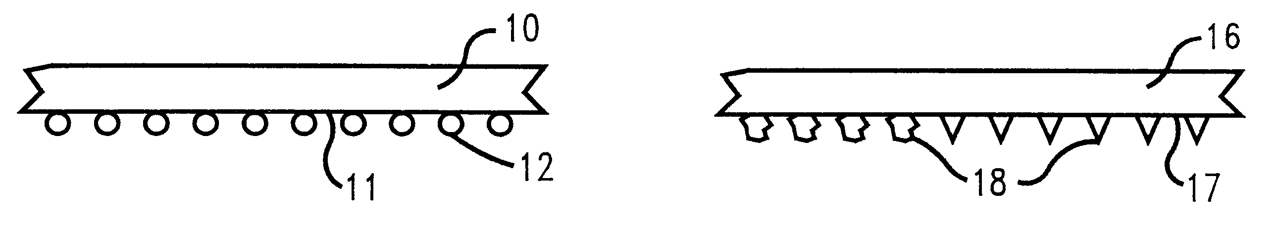
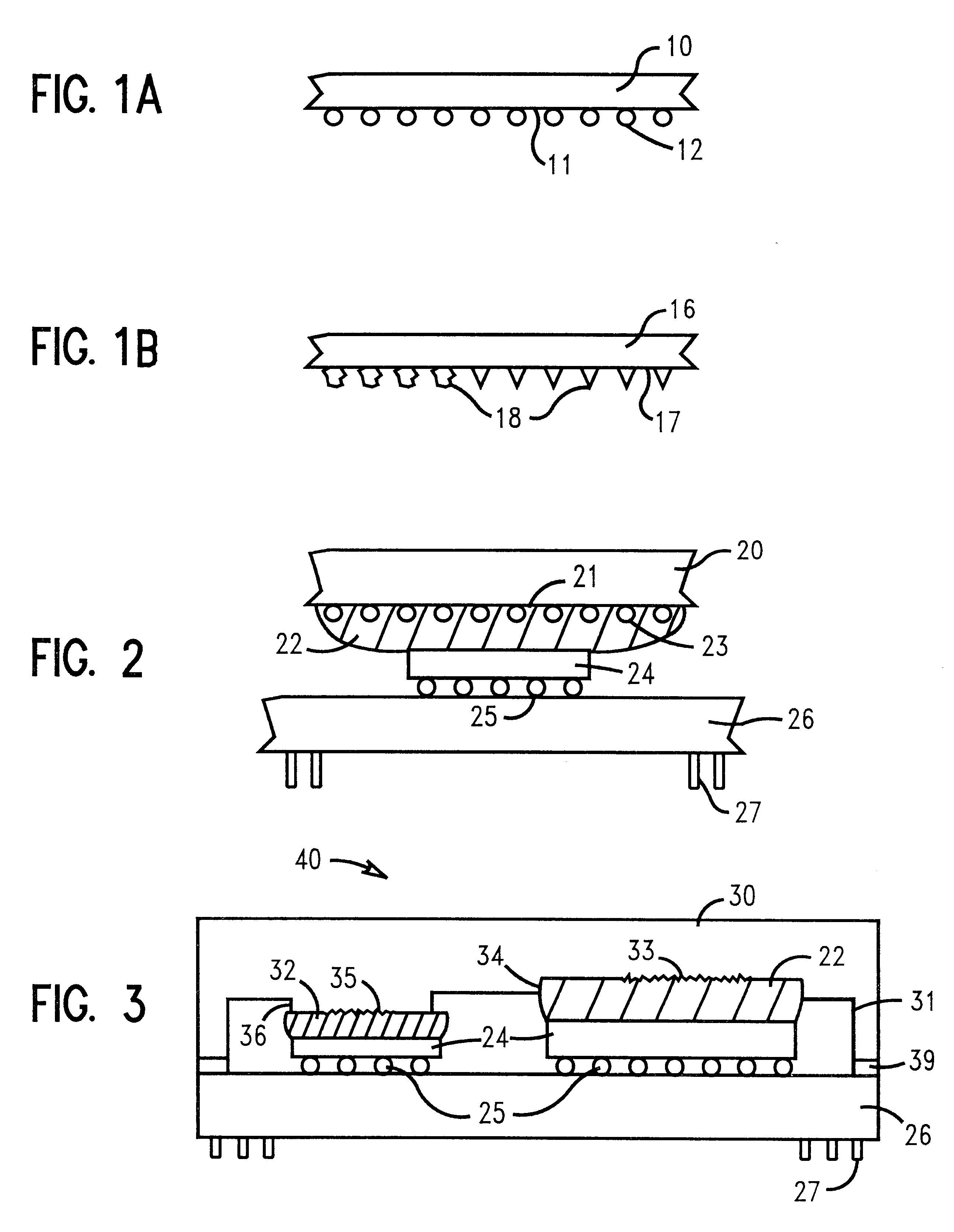
In a preferred embodiment, the cooling cap is made of aluminum, and on at least a portion of its internal surface alumina particles are embedded to be compatible with pastes containing alumina filler.
example 2
In an alternative embodiment, a different thermal paste utilizing different solids is used, and the cap is not made from the same material as one of the solids in the paste, but the surface is embedded with particles of the same material as used for one of the solids in the paste.
Login to View More PUM
| Property | Measurement | Unit |
|---|---|---|
| diameter | aaaaa | aaaaa |
| diameter | aaaaa | aaaaa |
| diameter | aaaaa | aaaaa |
Abstract
The present invention relates generally to a new method for improving the reliability of cooling designs using thermal paste to cool chips in semiconductor modules and structure thereof. More particularly, the invention encompasses a structure and a method that uses surface chemistry modification of the inside of the thermal cooling caps where it contacts thermal paste. The internal surface of the cap is modified by embedding particles that have the same chemical composition as one or more of the solids used in the thermal paste. The particles may be embedded in the cap by casting, grit blasting, or pressing the particles permanently into the surface.
Description
The present invention relates generally to a new method for improving the reliability of cooling designs using thermal paste to cool chips in semiconductor modules and structure thereof. More particularly, the invention encompasses a structure and a method that uses surface chemistry modification of the inside of the thermal cooling caps where it contacts thermal paste. The internal surface of the cap is modified by embedding particles that have the same chemical composition as one or more of the solids used in the thermal paste. The particles may be embedded in the cap by casting, grit blasting, or pressing the particles permanently into the surface.Semiconductor devices are becoming smaller and more dense with the evolution of new technology. However, increases in circuit density produce a corresponding emphasis on overall chip packaging strategies in order to remain competitive. Chip and substrate manufacturers are therefore constantly being challenged to improve the quality of t...
Claims
Login to View More Application Information
Patent Timeline
 Patent Type & AuthorityPatents(United States)
IPC IPC(8): H01L23/367H01L23/42H01L23/34H01L23/373
CPCH01L23/367H01L23/3733H01L23/3737H01L23/42H01L2224/16H01L2224/32245H01L2924/16152H01L2224/73253H01L2224/16227H01L2224/16225
InventorEDWARDS, DAVID L.COICO, PATRICK A.IRUVANTI, SUSHUMNAPOMPEO, FRANK L.SHERIF, RAED A.TOY, HILTON T.
OwnerINT BUSINESS MASCH CORP