Method and apparatus for measuring bias magnetic field for controlling magnetic domain of magnetoresistive effect element
a technology of magnetic field and control magnetic field, which is applied in the field of measuring bias magnetic field for controlling the magnetic domain of magnetoresistive effect elements, can solve the problems of affecting the sensitivity of the sensing mr element, and being difficult to apply this method to gmr elements like spin valve mr elements by the structure of pinned
- Summary
- Abstract
- Description
- Claims
- Application Information
AI Technical Summary
Problems solved by technology
Method used
Image
Examples
second example
FIGS. 8a to 8c show .rho.-H loop characteristics curves obtained by a second example of the measurement of the magnetic domain control bias according to the present invention. FIG. 8a represents the loop under the sense current of I.sub.s =5 mA, FIG. 8b under the sense current of I.sub.s =10 mA and FIG. 8c under the sense current of I.sub.s =17 mA, respectively.
This second example of the measurement was done onto different MR element sample on the same wafer used in the first example.
Comparing FIGS. 8a to 8c with each other, it is apparent that the loop becomes symmetrical in accordance with the increase of the sense current. This is because the magnetization of the pinned layer can comparatively freely rotate against the externally applied magnetic field due to joule heat of the sense current flow. When the sense current is I.sub.s =17 mA, an almost symmetrical loop is obtained. In this .rho.-H loop, the strength of the externally applied magnetic filed is 548.0 Oe in the positive ...
third example
FIGS. 9a to 9c show .rho.-H loop characteristics curves obtained by a third example of the measurement of the magnetic domain control bias according to the present invention. FIG. 9a represents the loop under the sense current of I.sub.s =5 mA, FIG. 9b under the sense current of I.sub.s =10 mA and FIG. 9c under the sense current of I.sub.s =15 mA, respectively.
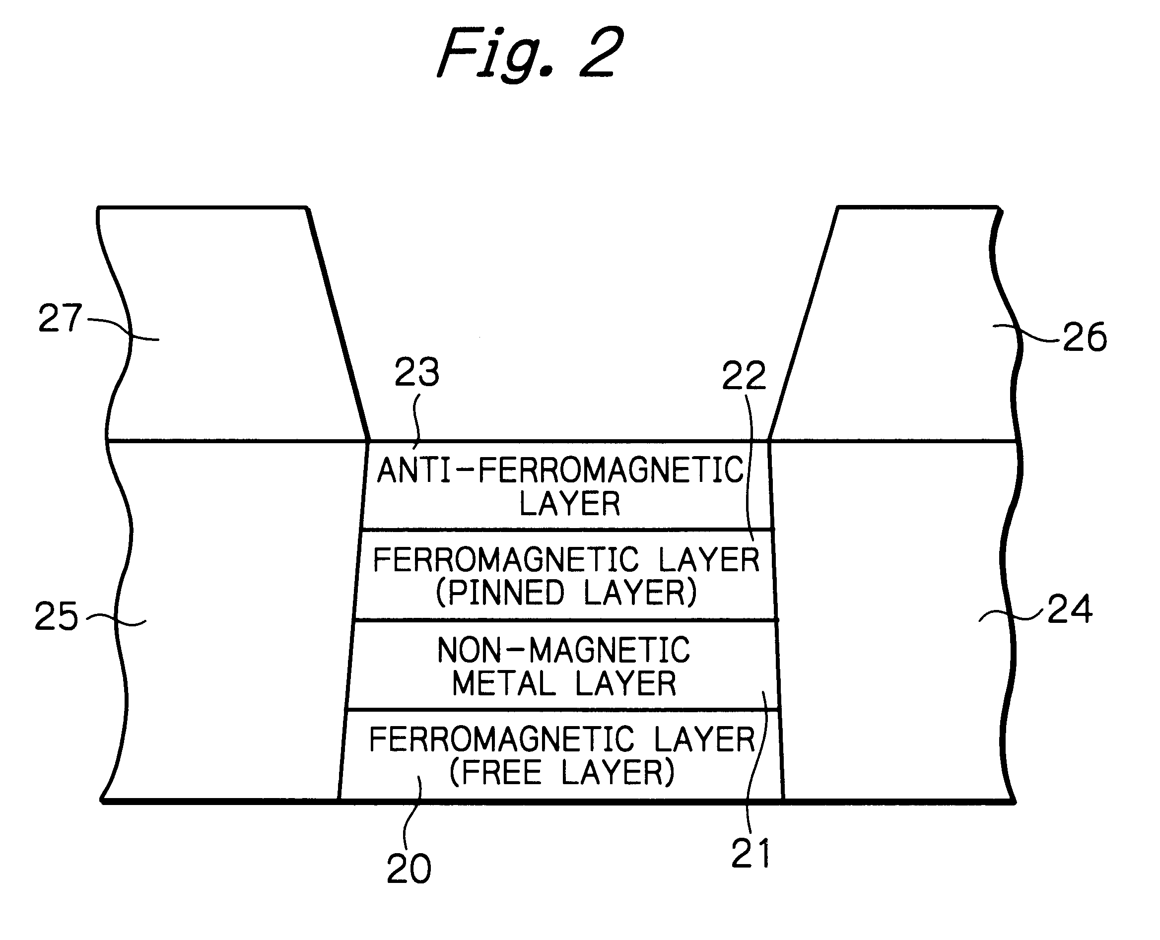
This third example is a case of a spin valve MR element (with no shield layer) with a spin valve multi-layered structure which consists of Ta layer (thickness 5 nm) / NiFe layer (8 nm) / Co layer (1 nm) / Cu layer (2.7 nm) / Co layer (20 nm) / RuRhMn layer (11 nm) / Ta layer (5 nm). To the spin valve multi-layered structure, longitudinal bias magnetic field is applied from hard magnet layers of PtCo (thickness 500 nm). The strength of the externally applied measurement magnetic field is 900 Oe, and the direction of this applied magnetic field is in parallel with the direction of the longitudinal bias magnetic field or the track width dire...
fourth example
FIGS. 10a to 10c show .rho.-H loop characteristics curves obtained by a fourth example of the measurement of the magnetic domain control bias according to the present invention. FIG. 10a represents the loop under the sense current of I.sub.s =5 mA, FIG. 10b under the sense current of I.sub.s =10 mA and FIG. 10c under the sense current of I.sub.s =14 mA, respectively.
This fourth example is a case of a spin valve MR element (with no shield layer) with a spin valve multi-layered structure which consists of Ta layer (thickness 5 nm) / NiFe layer (8 nm) / Co layer (1 nm) / Cu layer (2.7 nm) / Co layer (20 m) / RuRhMn layer (11 nm) / Ta layer (5 nm). To the spin valve multi-layered structure, longitudinal bias magnetic field is applied from hard magnet layers of PtCo (thickness 200 nm). The strength of the externally applied measurement magnetic field is 900 Oe, and the direction of this applied magnetic field is in parallel with the direction of the longitudinal bias magnetic field or the track widt...
PUM
 Abstract
Description
Claims
Application Information
 - R&D
- Intellectual Property
- Life Sciences
- Materials
- Tech Scout
- Unparalleled Data Quality
- Higher Quality Content
- 60% Fewer Hallucinations
Browse by: Latest US Patents, China's latest patents, Technical Efficacy Thesaurus, Application Domain, Technology Topic, Popular Technical Reports.
© 2025 PatSnap. All rights reserved.Legal|Privacy policy|Modern Slavery Act Transparency Statement|Sitemap|About US| Contact US: help@patsnap.com


