Variable frequency oscillator circuit

a frequency oscillator and circuit technology, applied in continuous tuning, continuous tuning, instrumentation, etc., can solve the problems of limiting the versatility and tuning range of these known vfo circuits, and affecting the performance of the tank

Inactive Publication Date: 2001-07-03
LUCENT TECH INC
View PDF1 Cites 30 Cited by
  • Summary
  • Abstract
  • Description
  • Claims
  • Application Information

AI Technical Summary

Problems solved by technology

As such, currently employed VFO circuits, such as the circuit 5 of FIG. 1, are limited in that they only provide for the VFO frequency to be reduced downward from a set frequency, as opposed to also or alternatively being increased above the set frequency, thereby limiting the versatility and tuning range of these known VFO circuits.
Although it may be possible, to an extent, to over-des

Method used


Image

  • Variable frequency oscillator circuit
  • Variable frequency oscillator circuit

Examples


Embodiment Construction

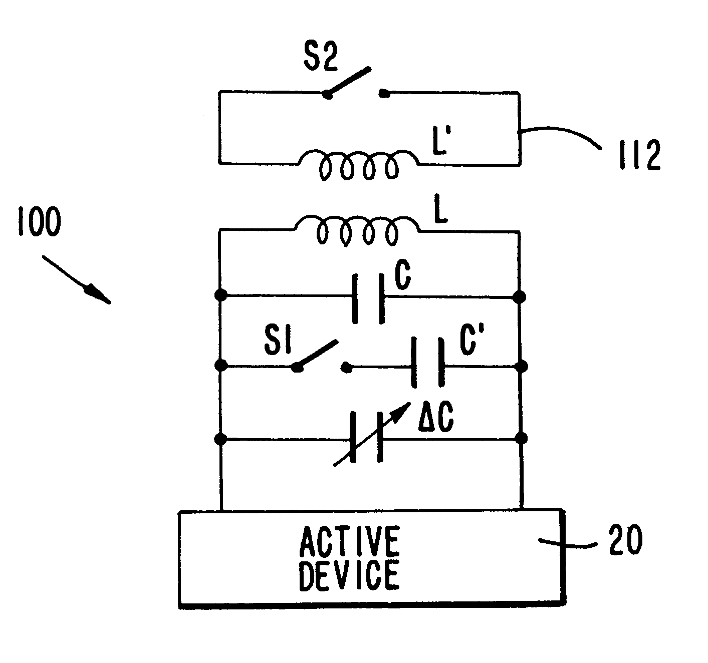
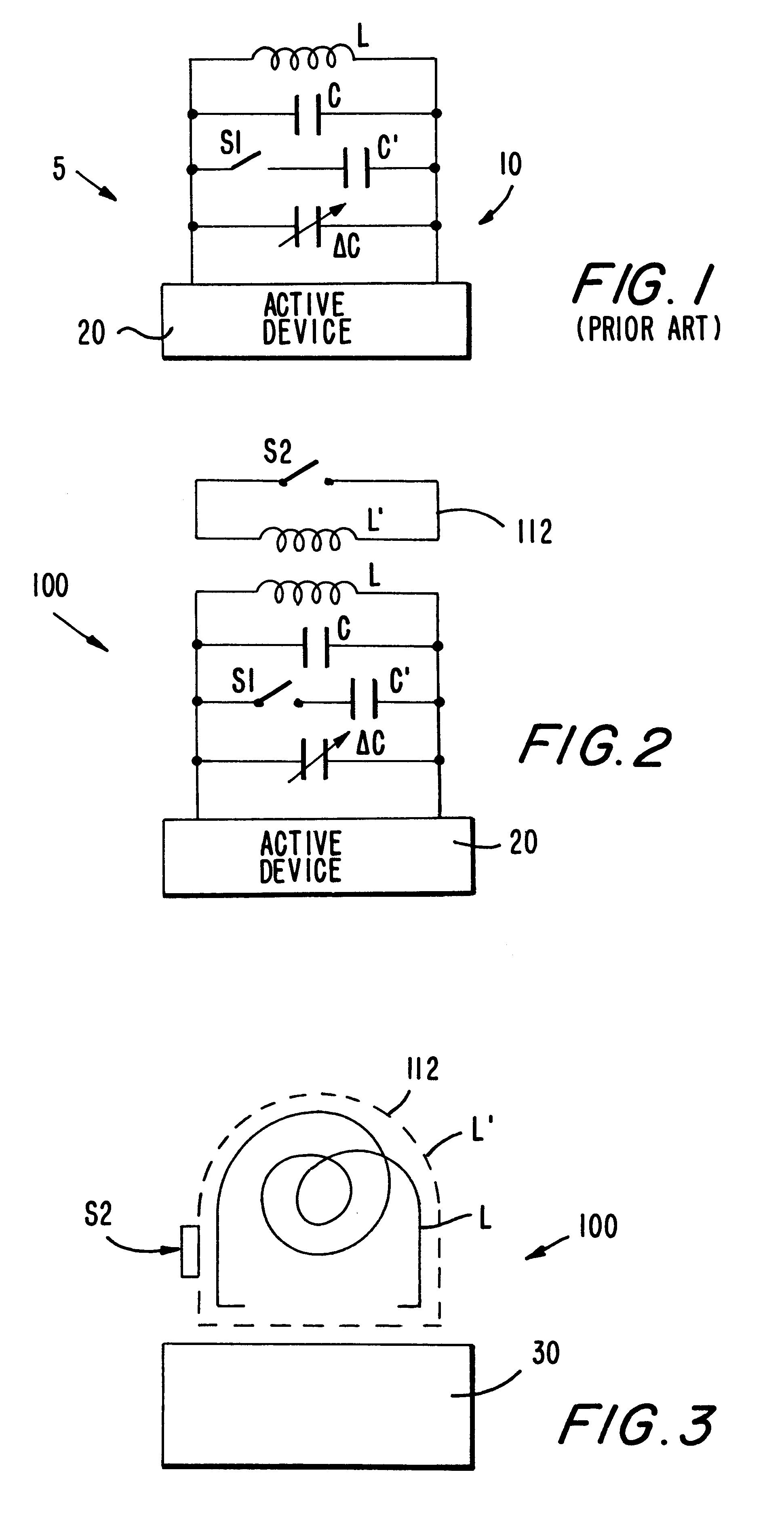
A tank circuit 100 for use in a variable frequency oscillator (VFO) constructed in accordance with the present invention is shown in FIG. 2. Like the prior art tank circuit 10 discussed above, circuit 100 is typically used in connection with an active device 20, such for example as a transistor, and includes an LC arrangement having a fixed value tank inductor L and a fixed value tank capacitor C connected in parallel to each other. Also like the prior art circuit 10, circuit 100 includes a selectively engageable capacitor having a fixed capacitance C' which is connected to a switch S1 for selectively connecting the engageable capacitor to the circuit to increase the overall capacitance of the circuit by an amount C'; this causes the set frequency F of the circuit to be reduced by a fixed or step amount .DELTA.f'. Switch S1 may be implemented or operated in any manner known to those skilled in the art, such as by a MOSFET transistor. To provide for fine tuning of the overall VFO fre...


PUM


Abstract

A variable frequency oscillator (VFO) circuit having an increased frequency tuning range to selectively obtain operating frequencies above and below a set frequency. The circuit includes a tank inductor connected in parallel with a tank capacitor for primarily defining the set oscillating frequency of the VFO circuit. A switchable capacitor is included for selectively providing a predetermined step-wise decrease of the oscillating frequency to a frequency value below the set frequency of the circuit, and a varactor is included for accommodating selective tuning of the oscillating frequency within a range of frequency values below the set frequency. The inventive circuit selectively includes a switchable inductance element which is selectively electromagnetically coupled to the tank inductor to decrease the overall inductance value of the VFO circuit and, thereby, selectively increase the oscillating frequency above the set frequency value.

Description

1. Field of the InventionThe present invention pertains to variable frequency oscillators (VFOs) and, more particularly, to a VFO having an increased tunable frequency range.2. Description of the Related ArtCurrently employed variable frequency oscillators (VFOs) are manufactured to achieve a desired target frequency (F) and provide for a limited tuning range relative to the circuit operating frequency to accommodate for shifts caused during manufacture or as required for operation. This tuning range allows the operating frequency to be adjusted downward from an actual frequency value to a value closely proximate the target frequency. Such VFOs include a tank circuit and an active device, such as a transistor, connected to a control box for adjusting the VFO frequency.A known prior art VFO circuit 5 is shown in FIG. 1 having a tank circuit 10 connected to an active device 20. The tank 10 employs an LC oscillator circuit having a tank inductor L with a fixed inductance connected in p...

Claims


Application Information

Patent Timeline
IPC IPC(8): H03B5/08H03B1/00
CPCH03B5/08H03B2201/025H03B2201/0216H03B2201/0208
Inventor WANG, HONGMO
Owner LUCENT TECH INC
Why Eureka
Try Eureka