Backlight for correcting diagonal line distortion

a backlight and diagonal line technology, applied in the field of backlight, can solve the problems of lack of ability to control the angle of light distribution, large waste of light energy produced by the backlighting system, and the lack of desired light energy intensity or brightness of the scattering backlighting system

Inactive Publication Date: 2001-07-03
LUMINIT
View PDF19 Cites 136 Cited by
  • Summary
  • Abstract
  • Description
  • Claims
  • Application Information

AI Technical Summary

Problems solved by technology

While a scattering backlighting system offers the ability, by controlling the distribution of the scattering media on the scattering surface, to control the light distribution, it does not offer an ability to control the angle of light distribution.
Much of the light energy produced by the backlighting system is wasted because it is scattered in directions that are not useful to a viewer or user of the LCD display.
Because much of the light energy is not directed to the user and thus wasted, scattering backlighting systems lack the desired light energy intensity or brightness.
The correlation of input light rays to output light rays in a non-scattering backlighting system may also lead to a potential disadvantage arising from imaging at the light input appearing at the light output.
If there is any distortion of the light energy at the input, this distortion will also appear at the output.
The distortion may result from roughness or discontinuity in the light source or the input optics.
Generally, such distortions will result in an area of non-uniform light intensity or a shadow in the output.
Another source of distortion is the construction of the walls of the light pipe perpendicular to the light source.
These walls must be made extremely smooth and flat or else they result in a distortion or shadow in the output.
A particular distortion that is observed in non-scattering backlighting systems is the formation of a diagonal line across the output plane of the backlight.
The distortions in each corner are due to manufacturing limitations in the construction of the light pipe.
While it is possible to polish and smooth the surfaces to reduce the appearance of such a distortion, these processes are time consuming and labor intensive and, the

Method used


Image

  • Backlight for correcting diagonal line distortion
  • Backlight for correcting diagonal line distortion
  • Backlight for correcting diagonal line distortion

Examples


Embodiment Construction

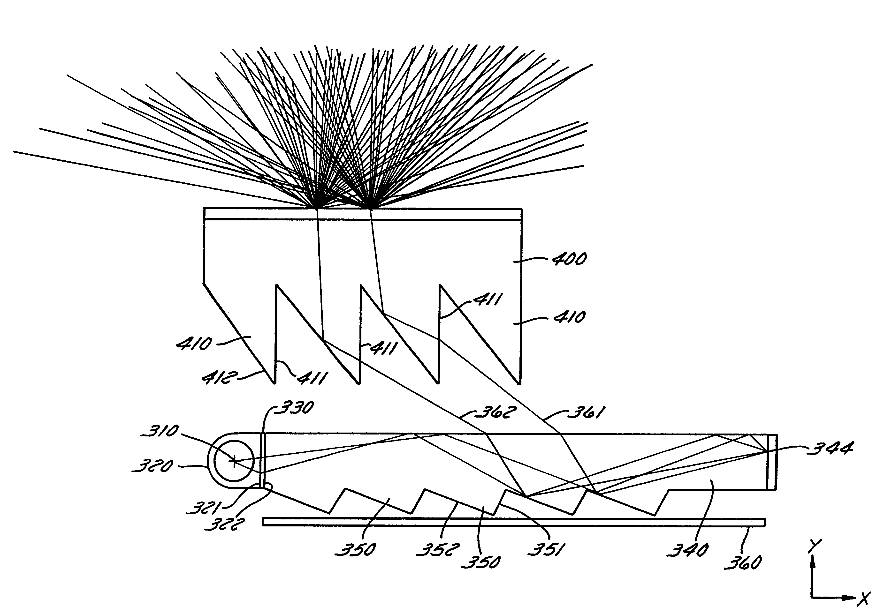
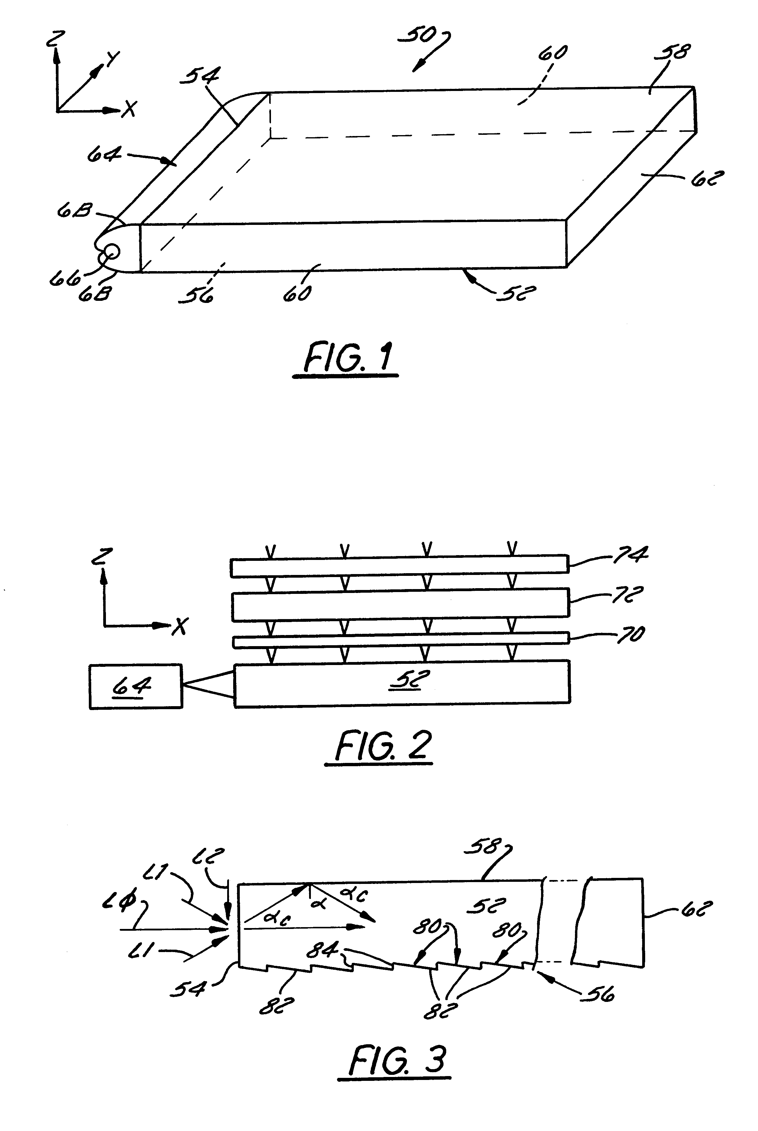
Referring to FIGS. 1 and 3, light source 66 is located within the space defined by the reflector surface 68. The light source 66 can be a cold cathode fluorescent bulb, a hot cathode fluorescent bulb, or any other type of light source as previously described. Light from the light source 66 is directed toward the waveguide collimator 52.

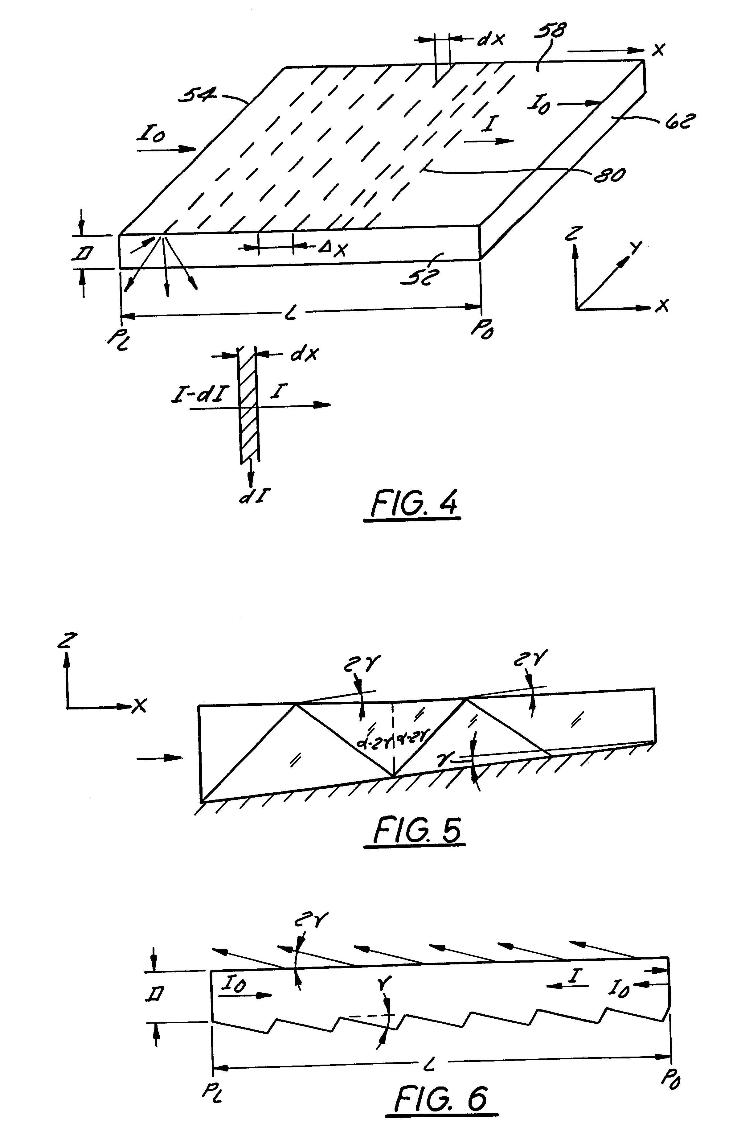
The light source 66 can be more generally referred to as an illumination source. The waveguide collimator 52 includes incident end or light input end 54. The bottom surface 56 of the waveguide collimator 52 is provided with a first plurality of substantially parallel optical elements or facets 80. Each of the first plurality of substantially parallel optical elements 80 includes a first facet 82 and a second facet 84. The waveguide collimator 52 also includes the top surface 58 and the far end 62.

With regard to the examples shown, and other embodiments, light from the illumination source can be directly incident upon the incident end. This means that ...


PUM


Abstract

A backlight apparatus has a collimating waveguide with a light input end, a top surface, a bottom surface, opposing sides, a far end opposite the light input end, and a total internal reflection critical angle for the material of the waveguide. A plurality of first facets are formed in the bottom surface distributed along the waveguide between the light input end and the far end. Each of the first facets has a first facet bottom surface which converges toward the top surface in a direction away from the far end relative to the top surface. A light scattering and reflective surface is disposed adjacent the far end of the collimating waveguide. The first facet bottom surfaces cause light rays entering the light input end to be totally internally reflected to the far end of the collimating waveguide wherein the scattering and reflective surface at the far end reflects and scatters light rays incident thereon back toward the light input end. The first facet bottom surfaces then cause the light rays reflected from the far end to exit the top surface. The first facet bottom surfaces may be formed either as straight facets or as curved surface facets and may also be alternatively formed having a reflective material layer thereon.

Description

1. Field of the InventionThe present invention relates generally to a backlight such as is used in backlighting a flat panel liquid crystal display (LCD), and more particularly to a backlight having an optical input arranged to provide a uniform light distribution to the LCD.2. Description of the Related ArtFlat panel displays, such as liquid crystal displays or LCD's used in laptop computers, generally incorporate a backlighting system to illuminate a liquid crystal based display panel. Important requirements of the backlighting system are to provide a substantially uniform light distribution and to provide a sufficiently intense light distribution over the entire plane of the display panel. To accomplish these requirements, the backlighting system typically incorporates a light pipe to couple light energy from a light source to the LCD panel. In scattering backlighting systems, an array of diffusing elements are disposed along one surface of the light pipe to scatter light rays in...

Claims


Application Information

Patent Timeline
IPC IPC(8): F21V5/00F21V7/04F21V8/00F21V7/00G01D11/28G02B5/04G02F1/1335G02B6/10G02F1/13G02B6/00G02B5/02G02F1/13357
CPCG02B6/0038G02B6/0061G02B6/0051Y10S385/901G02B6/0053G02F1/1335
Inventor LAINE, JEFFREY A.
Owner LUMINIT
Why Eureka
Try Eureka