Arc fault detection system

a fault detection and arc technology, applied in the direction of noise figure or signal-to-noise ratio measurement, process and machine control, instruments, etc., can solve the problems of conventional circuit breakers slipping, circuit breakers interrupting an electric circuit, corroded, worn or aged wiring, etc., to achieve the effect of reliably detecting arc fault conditions

Inactive Publication Date: 2001-07-10
SQUARE D CO
View PDF174 Cites 136 Cited by
  • Summary
  • Abstract
  • Description
  • Claims
  • Application Information

AI Technical Summary

Benefits of technology

It is an object of the present invention to provide an arc fault detection system and method which reliably detects arc fault conditions which may be ignored by conventional circuit interrupters.
Another object of the invention is to provide an arc fault detection system which utilizes a minimum number of highly reliable electronic signal processing components, such as a microcontroller, to perform most of the signal processing and analyzing functions, so as to be relatively simple and yet highly reliable in operation.

Problems solved by technology

Typically, circuit breakers interrupt an electric circuit due to a disconnect or trip condition such as a current overload or ground fault.
A ground fault trip condition is created by an imbalance of currents flowing between a line conductor and a neutral conductor which could be caused by a leakage current or an arcing fault to ground.
However, arcing faults may not cause a conventional circuit breaker to trip.
There are many conditions that may cause an arcing fault.
For example, corroded, worn or aged wiring, connectors, contacts or insulation, loose connections, wiring damaged by nails or staples through the insulation, and electrical stress caused by repeated overloading, lightning strikes, etc.
These faults may damage the conductor insulation and cause the conductor to reach an unacceptable temperature.

Method used


Image

  • Arc fault detection system
  • Arc fault detection system
  • Arc fault detection system

Examples


Embodiment Construction

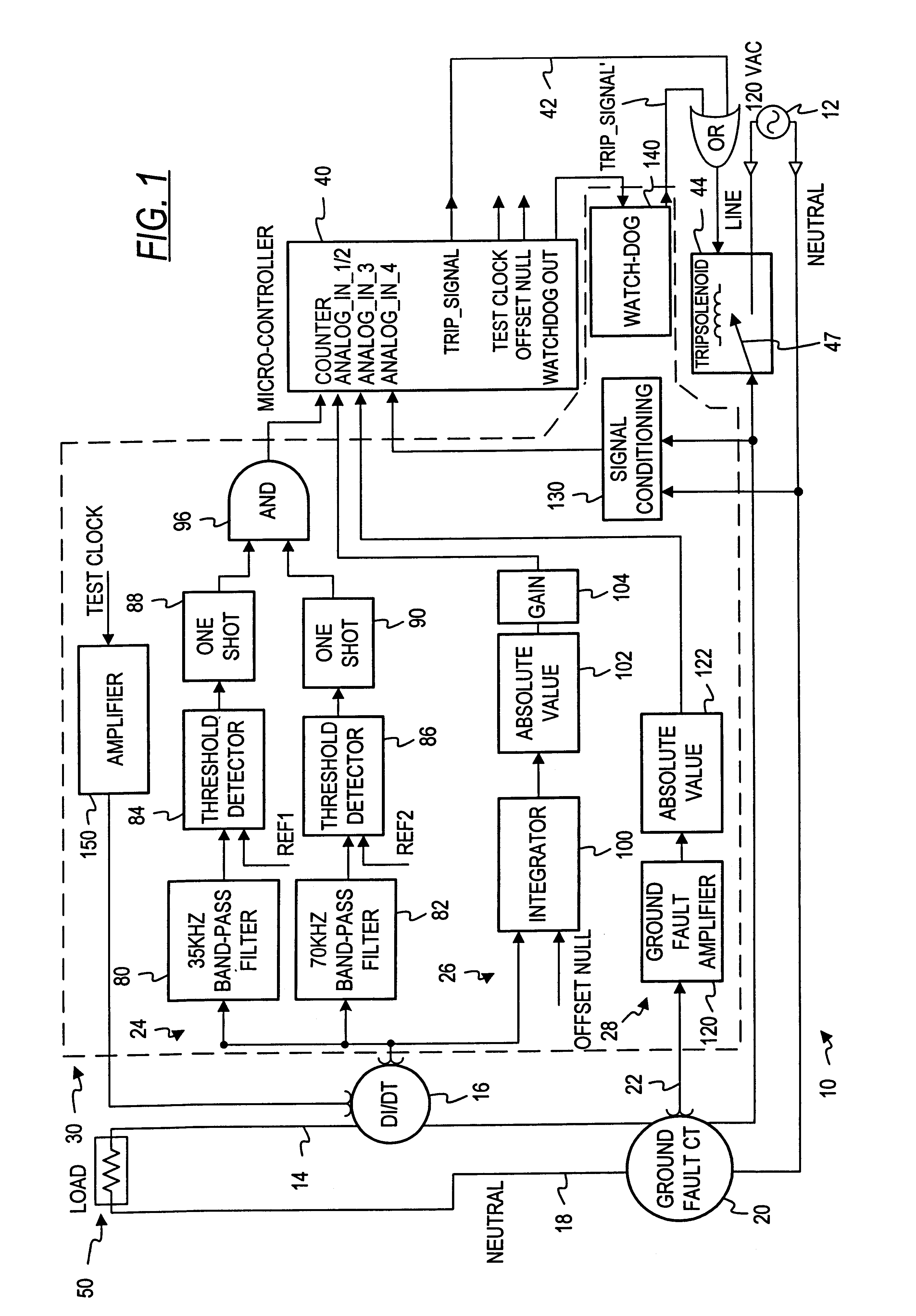
Referring now to the drawings in initially to FIG. 1, there is shown in block form a novel electrical fault detector system in accordance with the invention, and designated generally by the reference numeral 10. In the illustrative example, the fault detection system 10 is associated with an electrical circuit such as a 120 VAC circuit 12 which is to be monitored for faults. Of course, the invention is not limited to use with a 120 VAC circuit. At least one sensor 16 is provided in association with the 120 VAC circuit 12 for producing a signal representative of a signal condition, such as power, voltage or current in the 120 VAC circuit 12. In the illustrated embodiment, this sensor 16 comprises a current rate of change sensor (di / dt). A line conductor 14 of the 120 VAC circuit 12 passes through the rate of change current sensor (di / dt) 16 which produces a current input signal representative of the rate of change of current flow in the line conductor 14. In the illustrative embodime...


PUM


Abstract

An arc fault detector system detects arcing faults in an electrical distribution system by monitoring one or more conductors and producing an input signal representing one or more electrical signal conditions in the circuit to be monitored. This input signal is processed to develop signals representing the electrical current flow through the monitored circuit and broadband noise signal components. The system analyzes these signals to determine whether an arcing fault is present, and if so, outputs a trip signal which may be used directly or indirectly to trip a circuit breaker or other circuit interruption device.

Description

The present invention relates to the protection of electrical circuits and, more particularly, to the detection of electrical faults of the type known as arcing faults in an electrical circuit.The electrical systems in residential, commercial and industrial applications usually include a panelboard for receiving electrical power from a utility source. The power is then routed through protection devices to designated branch circuits supplying one or more loads. These overcurrent devices are typically circuit interrupters such as circuit breakers and fuses which are designed to interrupt the electrical current if the limits of the conductors supplying the loads are surpassed.Circuit breakers are a preferred type of circuit interrupter because a resetting mechanism allows their reuse. Typically, circuit breakers interrupt an electric circuit due to a disconnect or trip condition such as a current overload or ground fault. The current overload condition results when a current exceeds th...

Claims


Application Information

Patent Timeline
Patent Type & Authority Patents(United States)
IPC IPC(8): H01H71/12H02H1/00H02H3/08H02H3/10H02H1/06H02H3/44
CPCH02H1/0015H01H71/125H01H2300/03H02H1/06H02H3/105H02H3/44Y04S20/227Y04S20/14H01H2083/201Y02B70/3241Y02B90/224Y02B90/20Y02B70/30Y04S20/20
Inventor HAUN, ANDY A.COATS, ALAN G.WONG, KON B.DVORAK, ROBERT F.SCOTT, GARY W.
Owner SQUARE D CO
Why Eureka
Try Eureka