Eureka AIR delivers breakthrough ideas for toughest innovation challenges, trusted by R&D personnel around the world.

Optical systems employing stepped diffractive surfaces

a diffractive surface and optical system technology, applied in the field of optical systems employing stepped diffractive surfaces, can solve the problems of reducing the ability to control the change in the optical properties of the system with a change in temperature, reducing the ability to athermalize the refractive system composed of these materials with a kinoform, and providing a ray tracing techniqu

Inactive Publication Date: 2001-07-17
KSM ASSOCS
View PDF18 Cites 37 Cited by
  • Summary
  • Abstract
  • Description
  • Claims
  • Application Information

AI Technical Summary

Benefits of technology

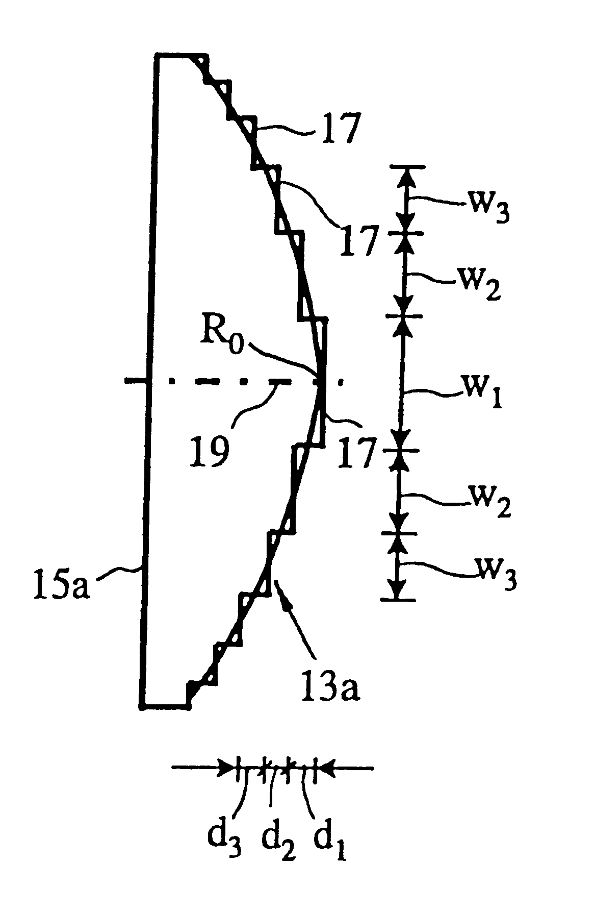
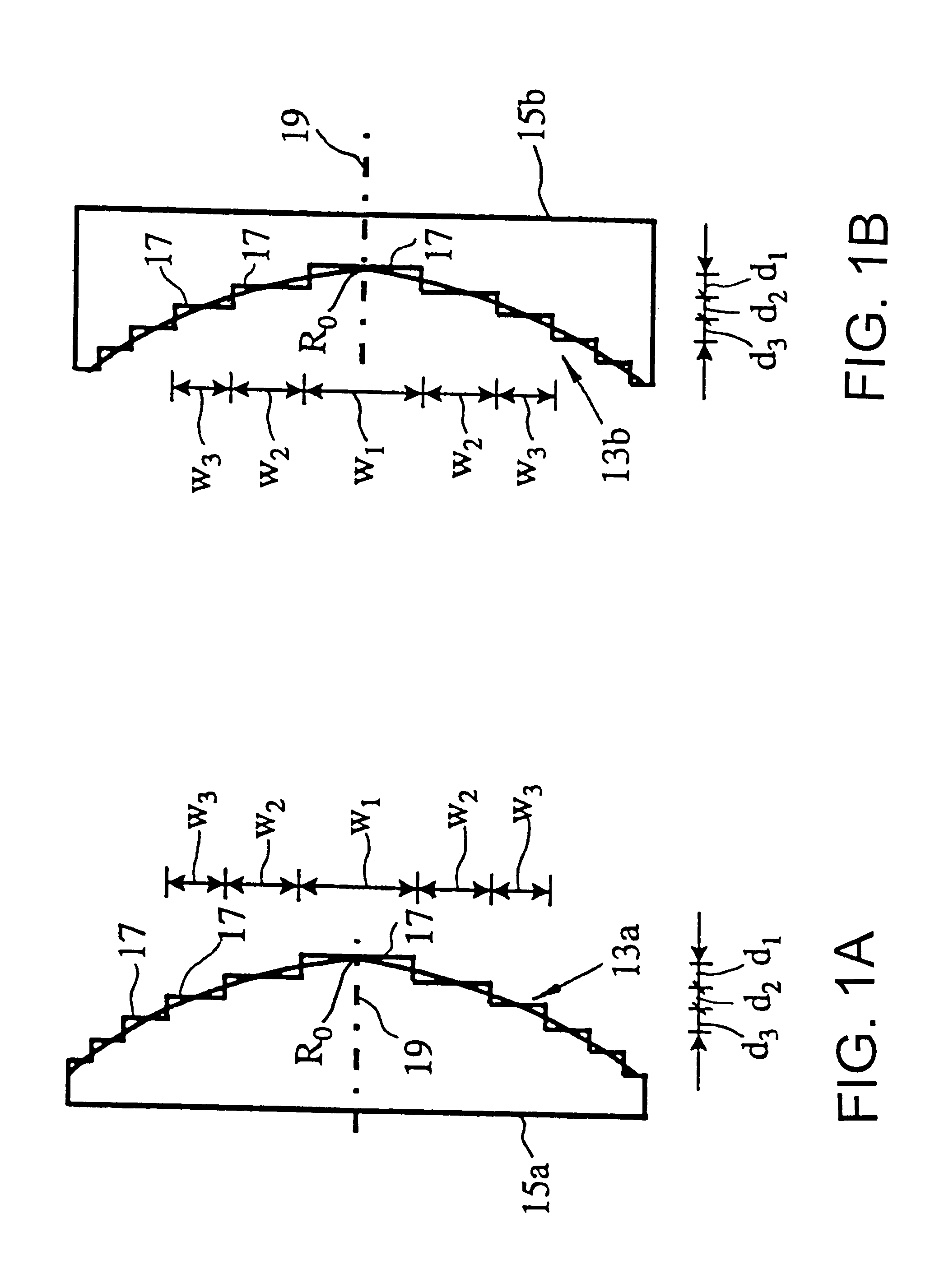
The compensation provided by the stepped diffractive surface will in general reduce variation in one or more specified optical properties of the optical system, e.g., image location in those cases where the optical system forms an image of an object, output power in those cases where the optical system is an optical source, focal length, magnification, etc., as a result of a change in the system's operating temperature. Preferably, the compensation will hold the one or more specified optical properties substantially constant to a desired extent for all operating temperatures within the range of temperatures for at least one operating wavelength, e.g., .lambda..sub.0. Alternatively, the compensation can result in a variation in an optical property in a desired manner, e.g., a substantially linear variation with temperature for an optical system which is designed to sense temperature.
The above approach cannot be used directly with a stepped diffractive surface since such surfaces are typically designed to have zero paraxial optical power at the system's nominal operating wavelength (.lambda..sub.0). In accordance with the invention, this problem is addressed by using the following expression for the effective paraxial optical power .PHI..sub.SDS.sup.Eff of a stepped diffractive surface: ##EQU6##

Problems solved by technology

For Si and Ge, the fact that the optothermal coefficients for kinoforms are much smaller than those for refractive components can make it difficult to athermalize a refractive system composed of these materials with a kinoform.
For these as well as the other materials in this table, the use of a kinoform can complicate the athermalization process since unlike stepped diffractive surfaces (see below), kinoforms introduce optical power into the system at the system's nominal operating wavelength (.lambda..sub.0).
In addition to not disclosing the use of stepped diffractive surfaces to achieve athermalization, none of the above prior disclosures provides a ray tracing technique which explicitly specifies the spacing and blaze angle of the steps of an SDS.
Among other things, the lack of such a ray tracing technique means that these references cannot account for the actual physical changes to the microstructure of the surface which occur as a result of a change in temperature.

Method used


Image

  • Optical systems employing stepped diffractive surfaces
  • Optical systems employing stepped diffractive surfaces
  • Optical systems employing stepped diffractive surfaces

Examples


example

FIG. 3A shows a refractive singlet having surfaces S1 and S2. The prescription for this lens is set forth in the first column of Table 2, where surface S2 is defined by the equation: ##EQU29##

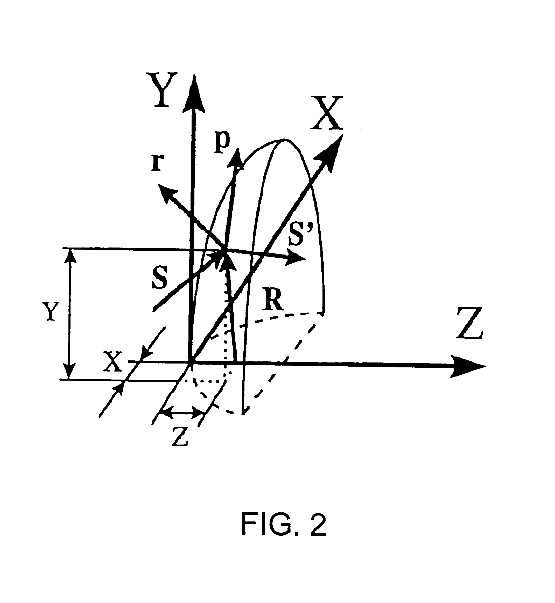
where "r" is a radial coordinate measured from the lens' optical axis and "z" is the surface's sag.

The calculated thermal behavior of the lens of FIG. 3A is shown in FIG. 4A, where PX and PY are pupil (stop) coordinates and EX and EY are field coordinates. For perfect imaging, all rays go to the axis so that EX and EY are zero for all PX and PY values.

As shown in FIG. 4A, the refractive singlet of FIG. 3A achieves perfect imaging at 20.degree. C., but exhibits significant amounts of defocus as the temperature is increased to 45.degree. C. and 700.degree. C., the amount of defocus being proportional to the temperature change.

FIG. 3B shows an athermal hybrid singlet constructed in accordance with the invention. The prescription for this lens is set forth in the second column of Table 2. As shown ...


PUM


Abstract

Stepped diffractive surfaces (13) are used to reduce variations in the optical properties of an optical system as a result of a change in the temperature of all or a portion of the system. Such surfaces have optothermal coefficients which differ from the optothermal coefficients of both kinoforms and refractive elements. Accordingly, stepped diffractive surfaces can be combined with such elements to achieve overall thermal control of optical systems employing such elements.

Description

I. FIELD OF THE INVENTIONThis invention relates to optical systems employing stepped diffractive surfaces (SDSs). More particularly, in accordance with certain of its aspects, the invention relates to the athermalization of optical systems by means of one or more stepped diffractive surfaces.II. BACKGROUND OF THE INVENTIONA. AthermalizationAs known in the art, the optical properties of an optical system normally vary with changes in temperature as a result of: (i) changes in the indices of refraction of the optical materials used in the system, (ii) changes in the shape of the optical elements used in the system, (iii) changes in the dimensions of the housing used to hold the optical elements, and (iv) changes in the wavelength or frequency of the light source employed in the system.Such changes in optical properties with changes in temperature are undesirable and extensive efforts have been made to solve this problem, examples of which can be found in the following patents and lite...

Claims


Application Information

Patent Timeline
Patent Type & Authority Patents(United States)
IPC IPC(8): G02B5/18G02B27/00
CPCG02B5/1814G02B5/1876G02B5/1895G02B27/0037G02B27/4205G02B27/4216G02B27/4222G02B27/4266G02B27/4283G02B27/4211Y10S359/90
Inventor SOSKIND, YAKOV G.
Owner KSM ASSOCS
Why Eureka
Eureka Blog
Learn More