Leak location

a technology of leak location and location location, applied in the direction of material analysis using sonic/ultrasonic/infrasonic waves, structural/machine measurement, instruments, etc., can solve the problems of affecting the accuracy of leak location, so as to reduce the corruption of hyperboloid and improve the effect of results

Inactive Publication Date: 2001-07-31
STEST STRUCTURAL TESTING TECH
View PDF5 Cites 55 Cited by
  • Summary
  • Abstract
  • Description
  • Claims
  • Application Information

AI Technical Summary

Benefits of technology

If the full vector of ground movement has been measured rather than just the vertical movement, then these additional measurements can be used to assist in separating the different wave types to reduce corruption of the hyperboloid in time-distance s

Problems solved by technology

One common location method makes use of the fact that the leaking fluid often creates a noise, typically a hissing sound, which is conducted along the pipe as vibration.
Unfortunately, the sound levels can be grossly distorted by underground heterogenities

Method used


Image

  • Leak location
  • Leak location

Examples


Embodiment Construction

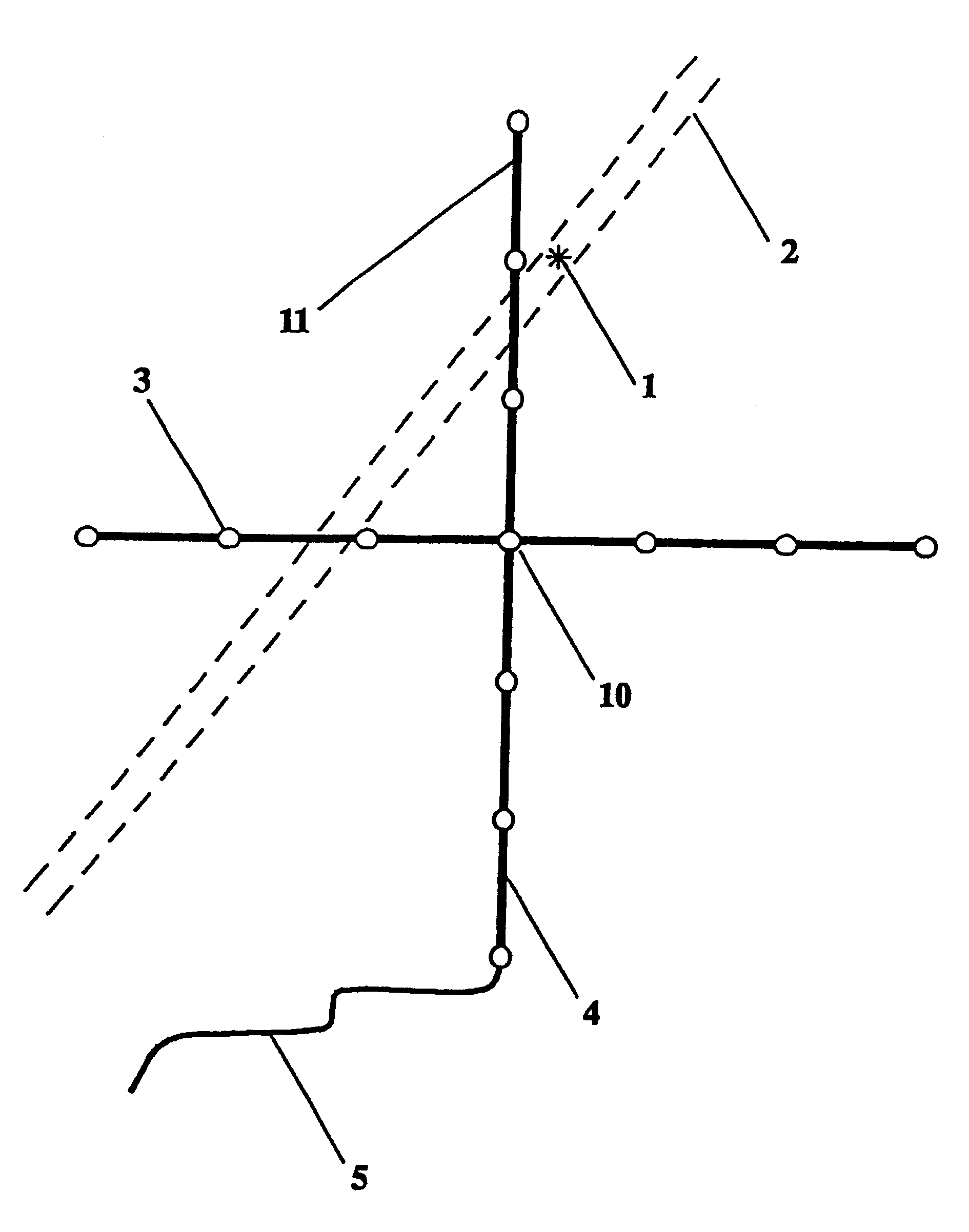
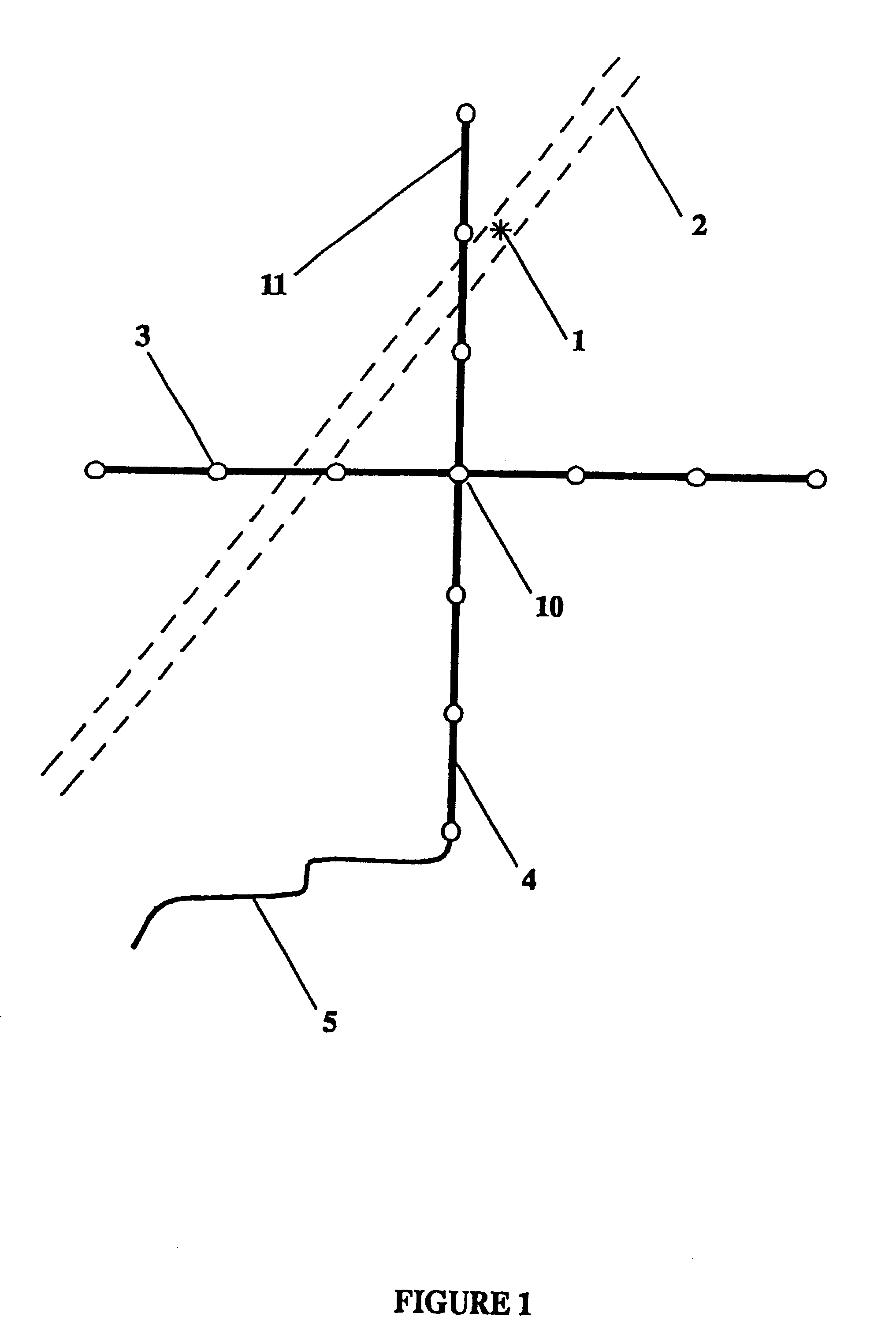
The embodiment of the invention shown in FIGS. 1-3 involves the use of discrete measurement sensors deployed as an array forming two orthogonal lines. The apparatus is an array 11 of sensitive accelerometers 3 connected by a robust connecting cable 4 and linked to a data collection system (not shown) by means of a data cable 5. The array 11 of accelerometers 3 is deployed on the surface of the ground (9: FIG. 2) so as to detect the location of a leak 1 in a pipe underground (2; shown in dashed outline). The accelerometers 3 are vibration-detecting devices which are specified to work up to high frequencies to measure the vertical motion of the ground surface 9. The array 11 has discrete equally-spaced sensitive accelerometers 3 on two lines at right angles.

Noise from the leak 1 may propagate to any one accelerometer 3 by a number of paths, some of which 6, 7, and 8 as shown in FIG. 3.

The spatial dimensions of the array 11 are chosen to ensure that sufficient resolution can be achieve...


PUM


Abstract

When an underground pipe carrying a fluid, such as a buried water-pipe, develops a leak the leak must first be located before it can be repaired. One common location method makes use of the fact that the leaking fluid often creates a noise, typically a hissing sound, which is transmitted through the ground, and although rapidly attenuated can be heard with suitable highly sensitive ground microphones and is therefore useful to field crews as a means of locating leaks. Unfortunately, the sound levels can be grossly distorted by underground heterogenities, and can easily be confused or even swamped by other sound sources above ground, and in general ground microphones used like this do not seem to be effective. The invention deals with the problems entailed in this technique by a method-and apparatus -which involves using semi-automated equipment to listen (either simultaneously or sequentially) to the leak sound source (1) from a multiplicity of different positions (as 3) spaced all around the sound source, and by then suitably combining and processing the received signals to provide the desired indication of the source's location.

Description

This invention is concerned with leak location, and relates in particular to the determination of the location of a leak of fluid in an underground pipe. It has regard especially to leak location by means of a surface detector array which detects ground motion.There are many situations in which an underground pipe carrying a fluid, a gas or a liquid, develops a leak, which leak must then be located and repaired. A good example is the case of water distribution pipes buried at a depth down to a few metres below ground. One common location method makes use of the fact that the leaking fluid often creates a noise, typically a hissing sound, which is conducted along the pipe as vibration. The sound is also transmitted through the ground. Although the sound is rapidly attenuated by the ground, it is possible to hear the sound with suitable highly sensitive ground microphones, and therefore ground microphones are often made available to field crews in the water industry as a means of iden...

Claims


Application Information

Patent Timeline
IPC IPC(8): G01M3/24
CPCG01M3/243G01M3/24
Inventor HARPER, MARK FRANCIS LUCIENTHOMPSON, MARTIN
Owner STEST STRUCTURAL TESTING TECH
Why Eureka
Try Eureka