Method and apparatus for operating a hydraulic drive system of a feller-buncher

a hydraulic drive and feller-buncher technology, applied in the field of feller-bunchers, can solve the problems of high stress on inability to transfer power between the mechanical drive system and the hydraulic system, and high cost and time-consuming maintenance and replacement of the drive shaft and the universal join

Inactive Publication Date: 2001-07-31
CATERPILLAR INC
View PDF22 Cites 62 Cited by
  • Summary
  • Abstract
  • Description
  • Claims
  • Application Information

AI Technical Summary

Problems solved by technology

A disadvantage to this type of mechanical drive arrangement is that the drive shaft and the universal joint are subjected to high stresses as the front frame is pivoted relative to the rear frame.
Maintaining or replacing the drive shaft and universal joint is both expensive and time consuming.
A disadvantage of the separate systems is that power cannot be transferred between the mechanical drive system and the hydraulic system.
A particular disadvantage of having separate systems is that is it difficult to coordinate t

Method used


Image

  • Method and apparatus for operating a hydraulic drive system of a feller-buncher
  • Method and apparatus for operating a hydraulic drive system of a feller-buncher
  • Method and apparatus for operating a hydraulic drive system of a feller-buncher

Examples


Embodiment Construction

While the invention is susceptible to various modifications and alternative forms, a specific embodiment thereof has been shown by way of example in the drawings and will herein be described in detail. It should be understood, however, that there is no intent to limit the invention to the particular form disclosed, but on the contrary, the intention is to cover all modifications, equivalents, and alternatives falling within the spirit and scope of the invention as defined by the appended claims.

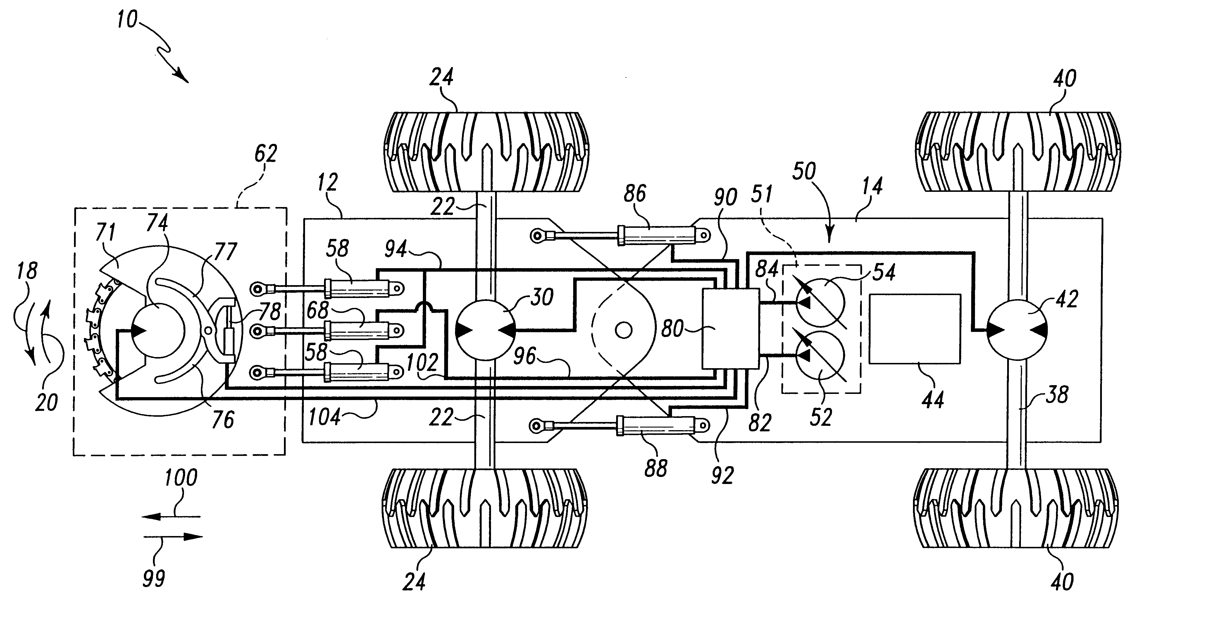
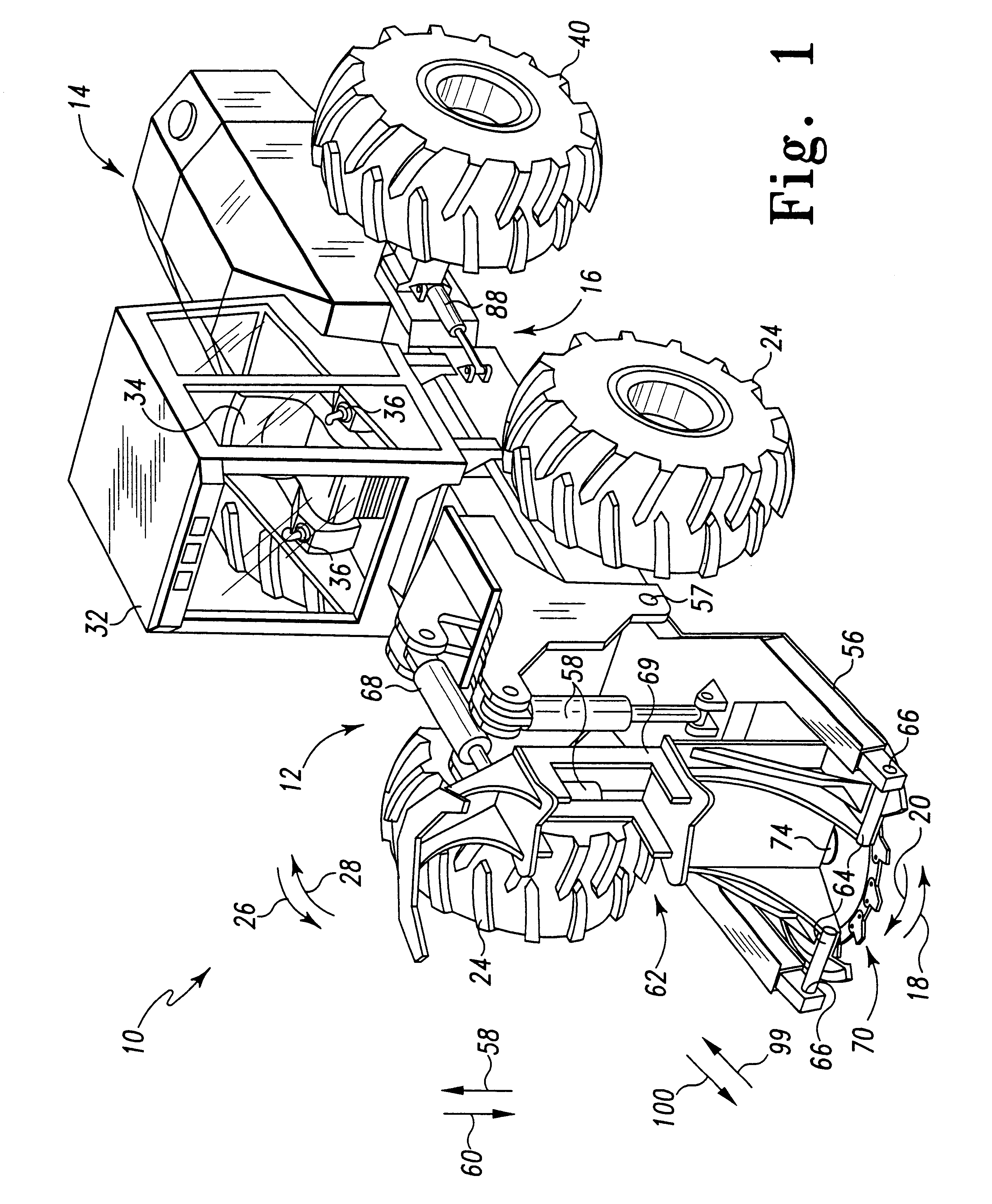
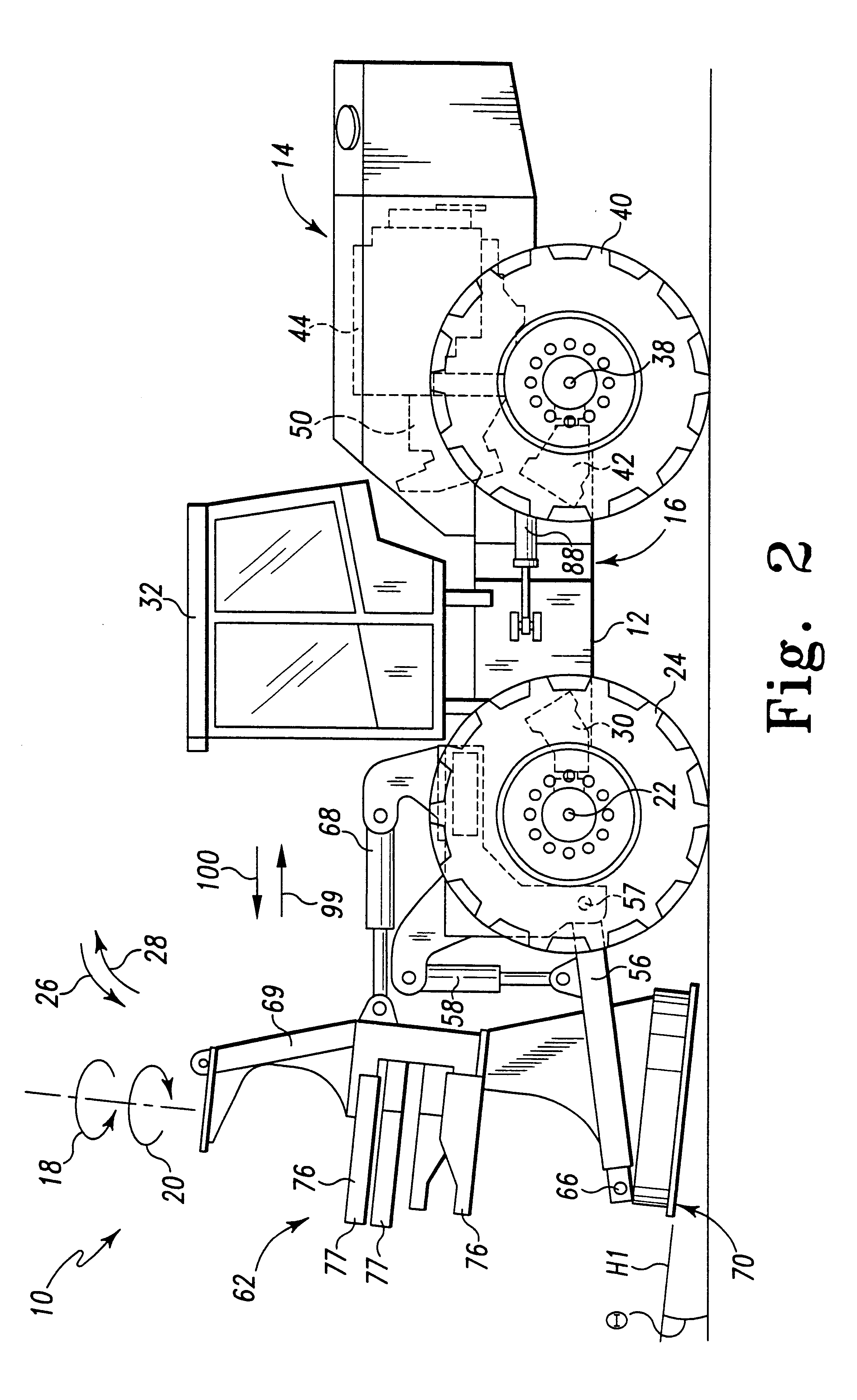
Referring now to FIGS. 1 and 2, there is shown a feller-buncher 10 that incorporates the features of the present invention therein. The feller-buncher 10 includes front frame 12 and a rear frame 14. The front frame 12 is pivotally connected to the rear frame 14 via a hitch 16. In particular, the hitch 16 allows the front frame 12 to pivot relative to the rear frame 14 in the general direction of arrows 18 and 20 of FIG. 1.

The front frame 12 is supported by a front axle 22. Two wheels 24 are m...


PUM


Abstract

A feller-buncher includes a first axle having a number of first wheels attached thereto and a second axle having a number of second wheels attached thereto. The feller-buncher also includes a first hydraulic motor operable to rotate the first axle and a second hydraulic motor operable to rotate the second axle. The feller-buncher also includes a first hydraulic pump operable to supply pressurized hydraulic fluid. Yet further, the feller-buncher includes a first flow sharing valve fluidly coupled to each of the first hydraulic pump, the first hydraulic motor, and the second hydraulic motor. The first flow sharing valve is configured to distribute the pressurized hydraulic fluid from the first hydraulic pump evenly between the first hydraulic motor and the second hydraulic motor, whereby the first axle and the second axle are driven at a substantially equal speed relative to one another. A method of operating a feller-buncher is also disclosed.

Description

TECHNICAL FIELD OF THE INVENTIONThe present invention relates generally to a feller-buncher, and more specifically to method and apparatus for operating a hydraulic drive system of a feller-buncher.BACKGROUND OF THE INVENTIONFeller-bunchers are used to fell, or cut down, a number of trees and then to bunch the trees together for transport. The bunched trees are then transported to a storage site for further processing. Typical feller-bunchers are articulated machines that include a front frame and a rear frame that are pivotally coupled by a hitch. The hitch allows the front frame to pivot relative to the rear frame so as to steer the feller-buncher. The front frame includes a front axle having a pair of wheels mounted thereon, and the rear frame includes a rear axle also having a pair of wheels mounted thereon.An engine mounted on the rear frame supplies mechanical power directly to a drop box. The drop box splits the power output from the engine between the front axle and the rear...

Claims


Application Information

Patent Timeline
IPC IPC(8): A01G23/08A01G23/00
CPCA01G23/081
Inventor HOLMES, ROBERT H.
Owner CATERPILLAR INC
Why Eureka
Try Eureka