Electro-acoustic device with a variable acoustic wave velocity piezoelectric substrate

a piezoelectric substrate and acoustic wave technology, applied in piezoelectric/electrostrictive/magnetostrictive devices, electrical apparatus, impedence networks, etc., can solve problems such as inability to directly couplage to devices with unbalanced inputs or outputs, lossy transitions, and inability to meet the needs of a number of applications

Inactive Publication Date: 2001-07-31
NOKIA TECHNOLOGLES OY
View PDF12 Cites 24 Cited by
  • Summary
  • Abstract
  • Description
  • Claims
  • Application Information

AI Technical Summary

Problems solved by technology

Thus, they are only capable of being directly coupled to devices having unbalanced inputs or outputs.
Thus, they are not particularly suitable for a number of applications, for example, an IF band-pass filter coupled to a balanced mixer.
Such transitions are typically lossy and furthermore take up space either on a circuit board upon which they are typically etched or by virtue of the lumped element components comprising the BALUN.
Additionally, when more than one coupled resonator filters are cascaded together to form multi-track, multi-pole filters, the necessary ground connections between respective tracks of the cascaded filters result in cross-talk which seriously degrades the perfo

Method used


Image

  • Electro-acoustic device with a variable acoustic wave velocity piezoelectric substrate
  • Electro-acoustic device with a variable acoustic wave velocity piezoelectric substrate
  • Electro-acoustic device with a variable acoustic wave velocity piezoelectric substrate

Examples


Embodiment Construction

Specific embodiments of the invention will now be described, by way of example only and with reference to the following drawings.

Although the specific embodiments disclosed below are described with reference to balanced input or output signals, the claimed invention is not so limited and encompasses differentially driven and arbitrarily phased signals.

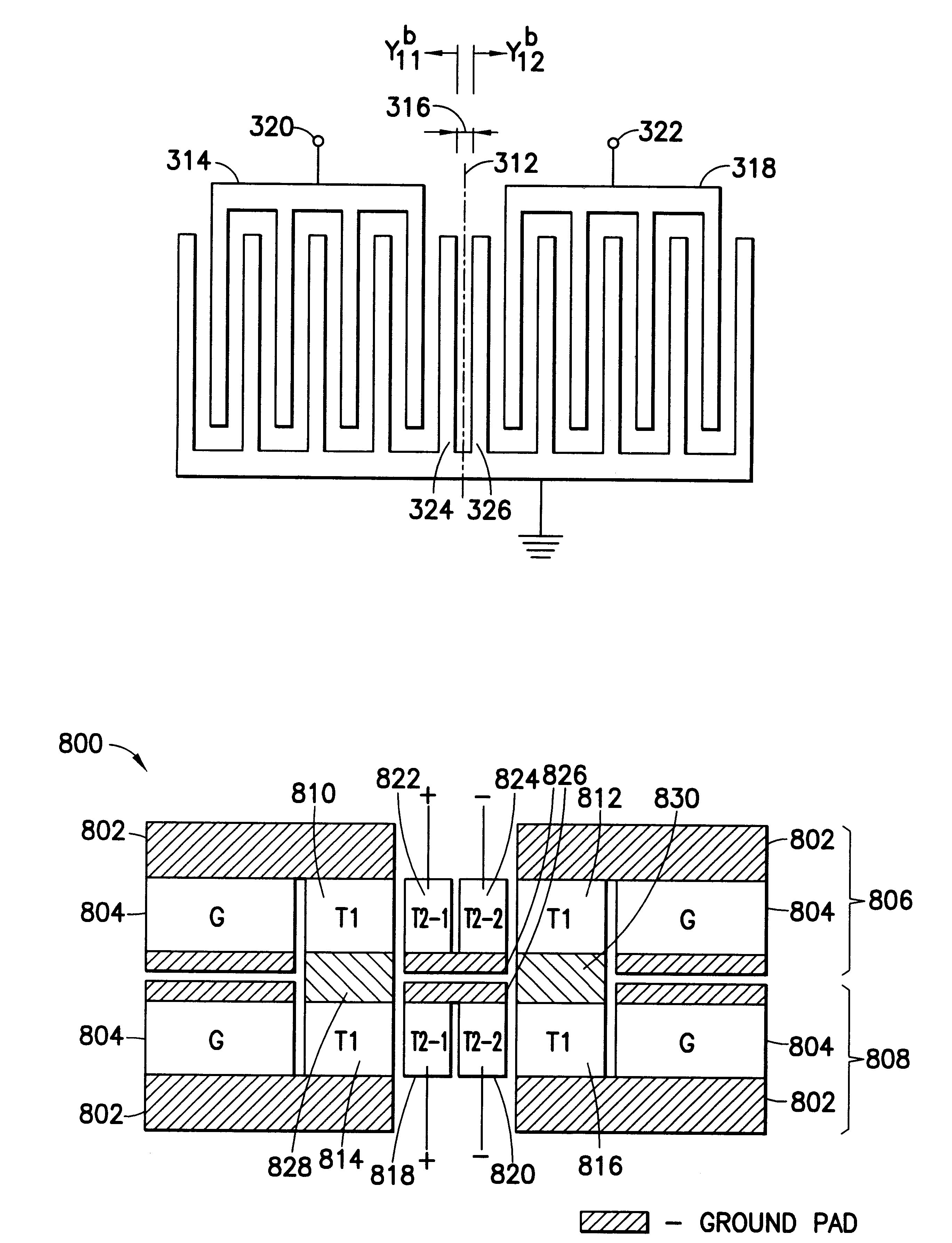
FIG. 3a shows a conventional IDT shown as a two electric port system. In principle a conventional IDT 302 comprising 4N+1 (N is a positive integer) fingers or electrode transducers 308 (forming 2N periods 310 ) can be considered to comprise a cascade of two separate IDTs 304, 306. Each separate IDT 304, 306 is 2N+1 electrode fingers long and they have a zero space (shown as dotted line 312 ) between them. The two electric port system can be expressed by a 2.times.2 admittance matrix [Y.sub.ij.sup.a ].

The current I.sub.1.sup.a, I.sub.2.sup.a flowing in respective separate IDTs 304, 306 can be given by the following equations;

I.sub.1.sup...


PUM


Abstract

There is described an electro-acoustic device, comprising a piezo-electric substrate and a first transducer and second transducer supported by the substrate and each including a pair of interdigital transducer electrode arrays, the electrodes of the arrays being interleaved with each other. The first and second transducer are disposed opposing each other in a propagation direction of acoustic waves excited by the first and second transducers. The first transducer has a first electric signal associated with and existing across, and the second transducer has a second electrical signal associated with it which has a different phase from the first electrical signal. The first and second transducers are spaced apart such that substantially in-phase acoustic waves propagating in the substrate and incident on the first transducer in-phase with the first electric signal and on the second transducer in-phase with the second electrical signal. Preferably, the first and second transducers are spaced apart by an integer number of half acoustic wavelengths corresponding to an operating frequency of the device. This permits differential or balanced driving of the device. There is further disclosed examples of such a device utilised in transversely and in-line coupled resonator filters to provide balanced or differential inputs or outputs thereto, and to facilitate cascade connected coupled resonator filters having no ground loops.

Description

The present invention relates to an electro-acoustic device, in particular but not exclusively, to a device for exciting Surface Acoustic Waves (SAW), or Surface Skimming Bulk Waves (SSBW).BACKGROUND OF INVENTIONTypically, communication systems such as mobile telephones or cellular radio telephone systems require frequency band-pass filters having frequency ranges from tens of Megahertz to Gigahertz, and having fractional bandwidths covering a range from less than 0.01% to about 5.0%. The foregoing frequency ranges and bandwidths are suitable for both centre frequency and bandwidth for the intermediate frequency (IF) and radio frequency (RF) stages of such communication systems.Well-known frequency filtering techniques for these frequency ranges are lumped LC filters, spiral or helical filters, dielectric filters and bulk acoustic wave filters. In addition to the foregoing there are also known electro-acoustic devices such as SAW coupled resonator filters, which have found particula...

Claims


Application Information

Patent Timeline
IPC IPC(8): H03H9/145H03H9/00H03H9/64
CPCH03H9/0038H03H9/0057H03H9/14552H03H9/6463H03H9/6433H03H9/6436H03H9/14588
Inventor HARTMANN, CLINTON S.CHEN, DONG PEI
Owner NOKIA TECHNOLOGLES OY
Why Eureka
Try Eureka