Method and apparatus for electric arc welding

a technology of electric arc welding and welding apparatus, which is applied in the direction of arc welding apparatus, welding apparatus, manufacturing tools, etc., can solve the problems of increasing the number of wires sticking ou

Inactive Publication Date: 2001-08-14
LINCOLN GLOBAL INC
View PDF10 Cites 63 Cited by
  • Summary
  • Abstract
  • Description
  • Claims
  • Application Information

AI Technical Summary

Benefits of technology

The present invention is particularly applicable for pipe welding wherein the measurement of the stick out provides information on changes in the gap of the root opening and / or the position of the electrode relative to the center line of the root joint. As the root opening increases, the weld puddle tends to fall through the gap into the inside of the pipe. The present invention detects the beginning of this event by sensing an increase in the electrode stick out. This increased stick out is used to reduce the heat of the weld puddle by reducing the weld current. This is done by decreasing the background or peak current, or both currents. Thus, the weld puddle temperature is reduced. This causes solidification of the molten metal in the bead to prevent the metal from falling through the gap. When the root gap is reduced, the sensed electrode stick out is also reduced because the molten metal does not pass through the gap. The molten puddle accumulates on the top of the gap. Thus, when a decrease in the stick out is sensed, the current is increased to increase the heat in the molten metal puddle in the joint. The hotter puddle penetrates into the narrow gap to cause proper fusion of the plate ends along the total depth of the gap.
After the root pass has been laid, measurement of the stick out can be used for seam tracking in accordance with another aspect of the invention. The sensed stick out information is used by the mechanism moving the weld head back and forth. The outboard position of the weld head can be detected as a decrease in the electrode extension. When the weld head moves to the outside portion of the joint, the stick out is small. As the electrode is moved across the joint, the electrode extension will vary in length with the shortest at the outside of the joint. As the electrode reaches one side of the joint it is reversed to move toward the other side. The electrode stick out will first increase and then decrease. The use of stick out information controls the weld head mechanism by signaling when the transverse movement of the electrode or weld head should be stopped and reversed. This action generates the serpentine pattern of the weld head during the welding operation and allows joint tracking.
In accordance with another aspect of the invention, the sensed stick out or electrode extension is used to reverse the movement of the weld head carrying the welding wire holder and moving in a serpentine pattern. This concept is used after the root bead has been laid. When using this aspect of the invention, the length of the stick out is sensed as the weld head carrying the wire is moved in a first direction transverse of the joint. When the sensed stick out is at a given reduced value, the transverse direction of the wire is reversed. This reversal is repeated at the opposite side of the joint so the electrode moves back and forth across the joint. This feature of the invention is extremely advantageous when the gap or root opening increases or decreases or when the path of the joint is not consistent. By using this aspect of the invention, the welding head tracks the actual path of the joint. Such joint tracking is not obtained when the transverse movement of the weld head automatically reverses at a fixed position, irrespective of the geometry of the joint.
In accordance with still another aspect of the present invention, the welding wire used in the welding apparatus and method is a flux cored electrode. Consequently, shielding gas is not required during the pipe welding operation. This is an advantage in remote geographical areas where pipe welding is normally performed.
The primary object of the present invention is the provision of an apparatus and method for controlling the heat directed to a puddle in an opened root welding process by sensing the stick out of the electrode and adjusting the current for changing the heat in the weld puddle. This objective solves the problem presented by variations in the gap at the open root of the joint.
Another object of the present invention is the provision of an apparatus and method, as defined above, which apparatus and method can be easily implemented to compensate for different profiles and different gaps in open root welding, as well as certain weld passes after the first root pass.

Problems solved by technology

This physical phenomenon results in an increase in wire stick out.

Method used


Image

  • Method and apparatus for electric arc welding
  • Method and apparatus for electric arc welding
  • Method and apparatus for electric arc welding

Examples


Embodiment Construction

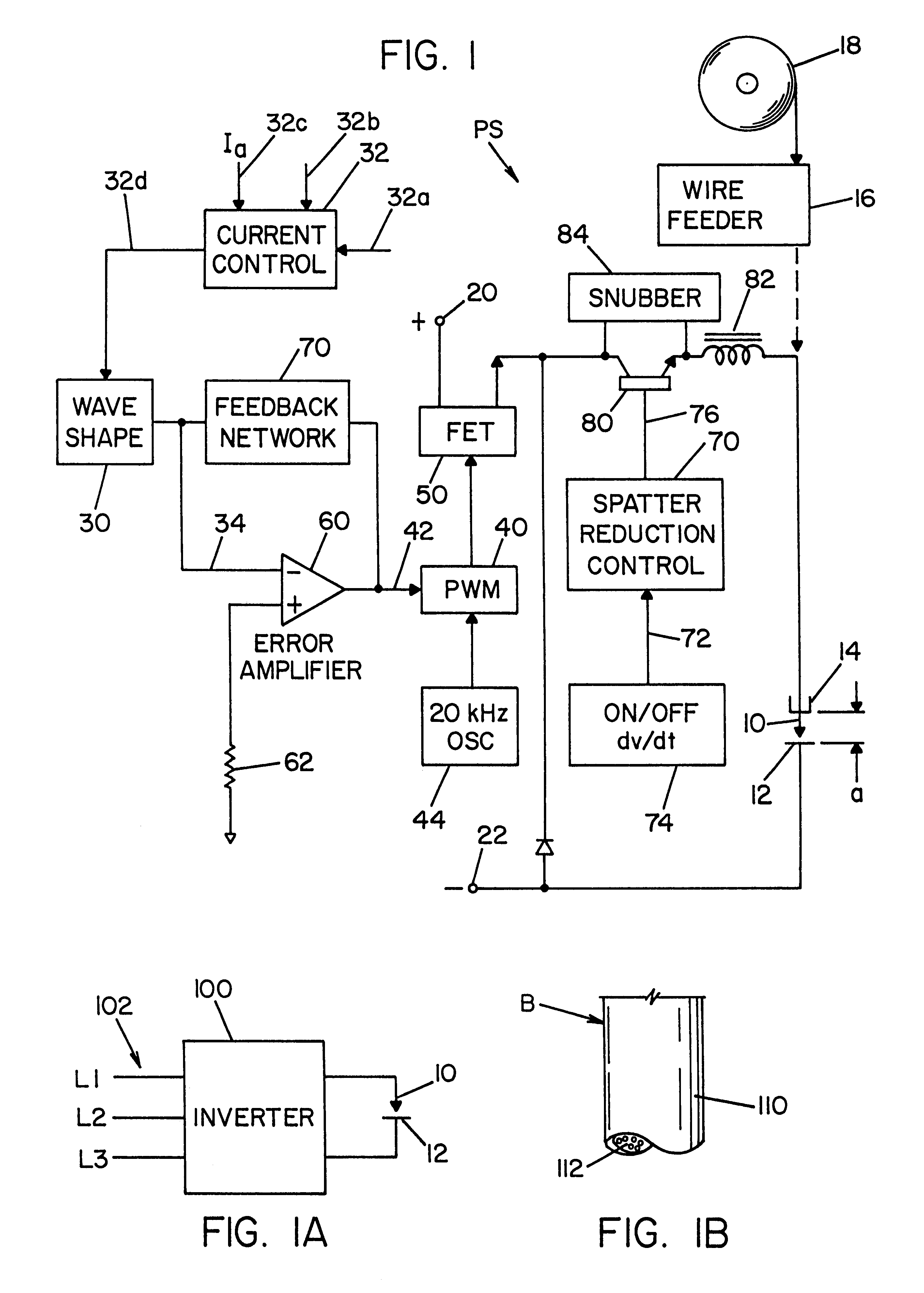
Referring now to the drawings wherein the showings are for the purpose of illustrating a preferred embodiment of the invention only and not for the purpose of limiting same, FIG. 1 shows a high frequency DC switching power supply PS for passing a welding current through welding wire 10 to workpiece 12 while the wire is supported in an electrical connector or holder 14. An appropriate wire feeder 16 pulls wire from a supply spool 18 at a rate determined by the setting of the power supply as adjusted by the operator or programmer. Holder 14 is connected to terminal 22 of the DC power supply PS to receive a DC pulse between terminals 20 and the opposite polarity terminal 22. The shape of the DC current pulse is determined by an appropriate wave shape circuit 30 having a current control 32 with an output 32d for adjusting the current of a welding cycle. This adjustment of current can involve changes in the maximum current, peak current, background current, etc. Wave shape circuit 30 is ...


PUM

PropertyMeasurementUnit
timeaaaaaaaaaa
timeaaaaaaaaaa
timeaaaaaaaaaa

Abstract

An electric arc welding apparatus for depositing molten metal from an advancing welding wire into a weld puddle in an open root between two juxtapositioned plates where the root extends in a welding path and is formed by converging walls terminating in generally parallel walls spaced to define a gap, which apparatus comprises a contact holder with a wire outlet, a switching power supply directing welding current to the wire as the wire passes from the outlet toward the open root, with the advancing wire defining an electrode stick out between the contact holder and the weld puddle, a circuit for sensing the length of the stick out, and control means for adjusting the welding current as a function of the sensed stick out length.

Description

The present invention relates to the art of electric arc welding and more particularly to a method and apparatus for electric arc welding which is particularly applicable to use in pipe welding, especially during the root pass in an open root joint.INCORPORATION BY REFERENCEAn electric arc welder of the short circuit type is known in the field as an STT welder sold by The Lincoln Electric Company of Cleveland, Ohio and generally described in the background of Stava U.S. Pat. No. 5,001,326, which patent is incorporated herein to illustrate details of the STT welder and certain features which are to be used in practicing the present invention. The invention uses a high frequency switching power supply, preferably an inverter. Various inverter based welders can be used; however, a representative welder is disclosed in Blankenship U.S. Pat. No. 5,351,175 incorporated herein as an inverter welder.BACKGROUND OF INVENTIONThe STT electric arc welder sold by The Lincoln Electric Company of C...

Claims


Application Information

Patent Timeline
Patent Type & Authority Patents(United States)
IPC IPC(8): B23K9/02B23K9/06B23K9/073B23K9/127B23K9/10B23K9/173B23K9/095
CPCB23K9/0216B23K9/1276B23K9/1056B23K9/0735
Inventor STAVA, ELLIOTT K.HSU, CHRISTOPHERNICHOLSON, PETER
Owner LINCOLN GLOBAL INC
Why Eureka
Try Eureka