Distributor-type fuel injection pump

Inactive Publication Date: 2001-08-28
ROBERT BOSCH GMBH
View PDF11 Cites 8 Cited by
  • Summary
  • Abstract
  • Description
  • Claims
  • Application Information

AI Technical Summary

Benefits of technology

The fuel injection pump of the invention has the advantage over the prior art that because of the diameter constriction in the connecting line, the effects that trip cavitation erosion are suppressed. Because of the diameter constriction, the outflow of fuel is throttled to a certain extent or at least in such a way that the fuel flowing out via the valve opening is rapidly opposed by a certain counterpressure, so that beyond the valve seat the outflowing fuel cannot expand, which would allow an unfavorable flow and would allow gas bubbles to form in the fuel. Before a continuous flow has built up in the outflow direction via the connecting line, the diameter constriction instantaneously makes a high throttling action available, which leads to a rapid pressure buildup in the second valve chamber.
In a further advantageous feature, the connecting line is oriented with its axis in the direction of the valve member, so that in this way a fuel exchange between the low-pressure region and the pump work chamber and vice versa can be effected in a streamlined way. Especially advantageously, in, the diameter constriction is designed such that it promotes a flow of fuel from the low-pressure region to the valve opening or the pump work chamber. The funnel-like design assures that the pump work chamber is supplied adequately and quickly with fuel during the intake phase of the distributor injection pump, without the diameter constriction having a harmful effect on the extent to which the pump work chamber is filled. Advantageously, the transitions on the inflow side to the pump work chamber can also be rounded. The embodiment as a diffusor allows further improvement in flow conditions. In the opposite direction, that is, for the emergence of fuel from the pump work chamber toward the low-pressure region, such provisions are not contemplated, in particular so that the initial throttling, while the flow through the connecting line has not yet been established, will be preserved in order to reduce the development of gas bubbles.
In a further advantageous feature, a plurality of connecting lines are provided, so that the above-described instantaneous counterpressure can build up uniformly to terminate the high-pressure injection directly after the reopening of the valve member, thus averting the formation of insular areas of gas bubbles. It is advantageous in this respect if one of the connecting lines is disposed opposite the pressure conduit leading away from the first valve chamber, so that the quantity of fuel flowing from the first pressure conduit into the second valve chamber via the valve opening will directly meet the throttled outlet from one of the connecting lines. In all cases, for forming the counterpressure it is important for a compensation piston to be disposed on the valve closing member, connected to the valve closing member vi a connecting tang and together with the second valve chamber forming an annular chamber. The chamber thus enclosed promotes the development of counterpressure and thus serves to reduce the tendency to cavitation.

Problems solved by technology

In this relief, because of the major pressure difference between the high- and low-pressure region, flow separations and flow recirculation zones can arise, and gas bubbles are formed in the fuel which in regions of relatively high pressures upon the ensuing implosion lead to material damage and so-called cavitation erosion, especially in the vicinity of the surrounding walls.
Over the long term, this can cause functional problems in the fuel injection pump, especially if these erosions extend to the valve seats themselves.

Method used


Image

  • Distributor-type fuel injection pump
  • Distributor-type fuel injection pump
  • Distributor-type fuel injection pump

Examples


Embodiment Construction

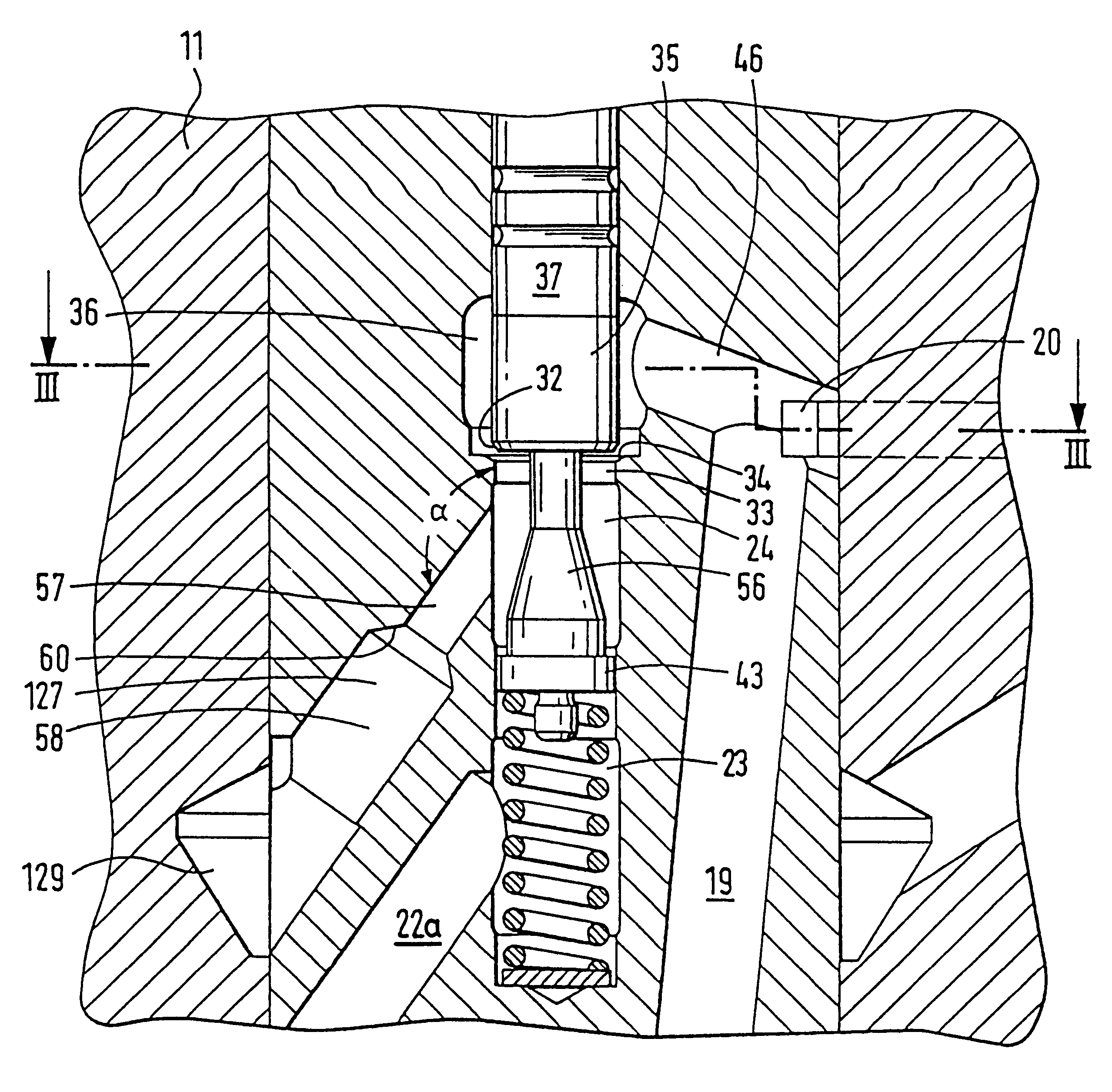
The fuel injection pump of the distributor type, shown in longitudinal section in fragmentary form in FIG. 1 of the drawing has a pump housing, not visible here, that is closed off in liquid-tight fashion by a pump head 10. A low-pressure region 45, not described further, is thus enclosed between the pump housing and the pump head and is at the same time a low-pressure supply region. A cylinder liner 14 is inserted into the pump head 10 and serves with its inner bore 22 to support a distributor shaft 11. The distributor shaft is driven to rotate by a drive shaft, not further shown, via a slaving means 12 and is supported so as to be fixed in the axial direction. In the region of a collar 9 protruding into the low-pressure region 45, there is at least one transverse bore 25, in which pump pistons 17 that between them enclose a pump work chamber 18 are supported. The pump pistons are driven to execute a supply stroke inward in the direction of the pump chamber 18 by a cam ring, not sh...


PUM


Abstract

A fuel injection pump of the distributor type which has a reciprocatingly driven pump piston that is load-bearing in a rotating distributor shaft which pumps fuel out of a pump work chamber to various fuel injection valves via a distributor opening. To control the duration of high-pressure injection, an electrically actuated valve is provided with a valve member in a valve chamber that communicates with the pump work chamber and from a second valve chamber, communicates with a low-pressure region. To terminate the high-pressure injection, the valve member makes a communication between the two valve chambers, whereupon the outflow of the fuel stream is controlled by disposing a diameter constriction in the connecting line, thus reducing any tendency to cavitation.

Description

PRIOR ARTThe invention is based on a fuel injection pump. In one such fuel injection pump, known from International Patent Disclosure WO 95 / 02760, a plurality of pump pistons located crosswise to the direction of rotation of the distributor are provided, in the manner of a radial piston pump with a pump work chamber enclosed between them. The connecting line used to supply fuel to the pump work chamber and to relieve it has a constant, unthrottled cross section in this known fuel injection pump. In these pumps, fuel is aspirated with the valve open over the entire intake stroke of the pump pistons, and the valve is then closed again to define the effective pumping stroke of the pump pistons. For a particular rotary angle range or time segment, the fuel injection pump then pumps fuel, which is brought to high injection pressure, to one fuel injection valve at a time, depending on the position of the distributor. To terminate this pumping or define the fuel injection quantity, the val...

Claims


Application Information

Patent Timeline
IPC IPC(8): F02M59/46F02M59/00F02M41/08F02M41/14
CPCF02M59/466F02M41/1411
Inventor NOTHDURFT, HEINZRODRIGUEZ-AMAYA, NESTORDUTT, ANDREASGREIF, HUBERT
Owner ROBERT BOSCH GMBH
Why Eureka
Try Eureka