Scleral prosthesis for treatment of presbyopia and other eye disorders

a technology of presbyopia and prosthesis, which is applied in the field of scleral prosthesis for treating presbyopia and other eye disorders, can solve the problems of not being able to restore not being able to adapt to the special needs of the prosthetic device used in treating presbyopia, and not being able to achieve the effect of restoring the accommodative power of the presbyopic ey

Inactive Publication Date: 2001-08-28
REFOCUS GROUP
View PDF14 Cites 175 Cited by
  • Summary
  • Abstract
  • Description
  • Claims
  • Application Information

AI Technical Summary

Benefits of technology

A further object is to provide a treatment for presbyopia by increasing the effective working distance of the ciliary muscle in the presbyopic eye.
A further object is to provide a treatment for presbyopia by increasing the radial distance between the equator of the crystalline lens and the ciliary body.
A further object is to provide a treatment for presbyopia by implanting in the sclera a plurality of prostheses which will increase the working distance of the ciliary muscle.
A further object is to provide a prosthesis for implanting in the sclera of an eye that will increase the working distance of the ciliary muscle.
A further object is to provide a prosthesis for implanting in the sclera of an eye that will increase the diameter of the ciliary body generally in the equatorial plane of the crystalline lens.

Problems solved by technology

According to the conventional view, it is not possible by any treatment to restore the accommodative power to the presbyopic eye.
However, none of these known devices have been used for surgical treatment of presbyopia, and none have been adapted to the special needs of prosthetic devices used in treating presbyopia.

Method used


Image

  • Scleral prosthesis for treatment of presbyopia and other eye disorders
  • Scleral prosthesis for treatment of presbyopia and other eye disorders
  • Scleral prosthesis for treatment of presbyopia and other eye disorders

Examples


first embodiment

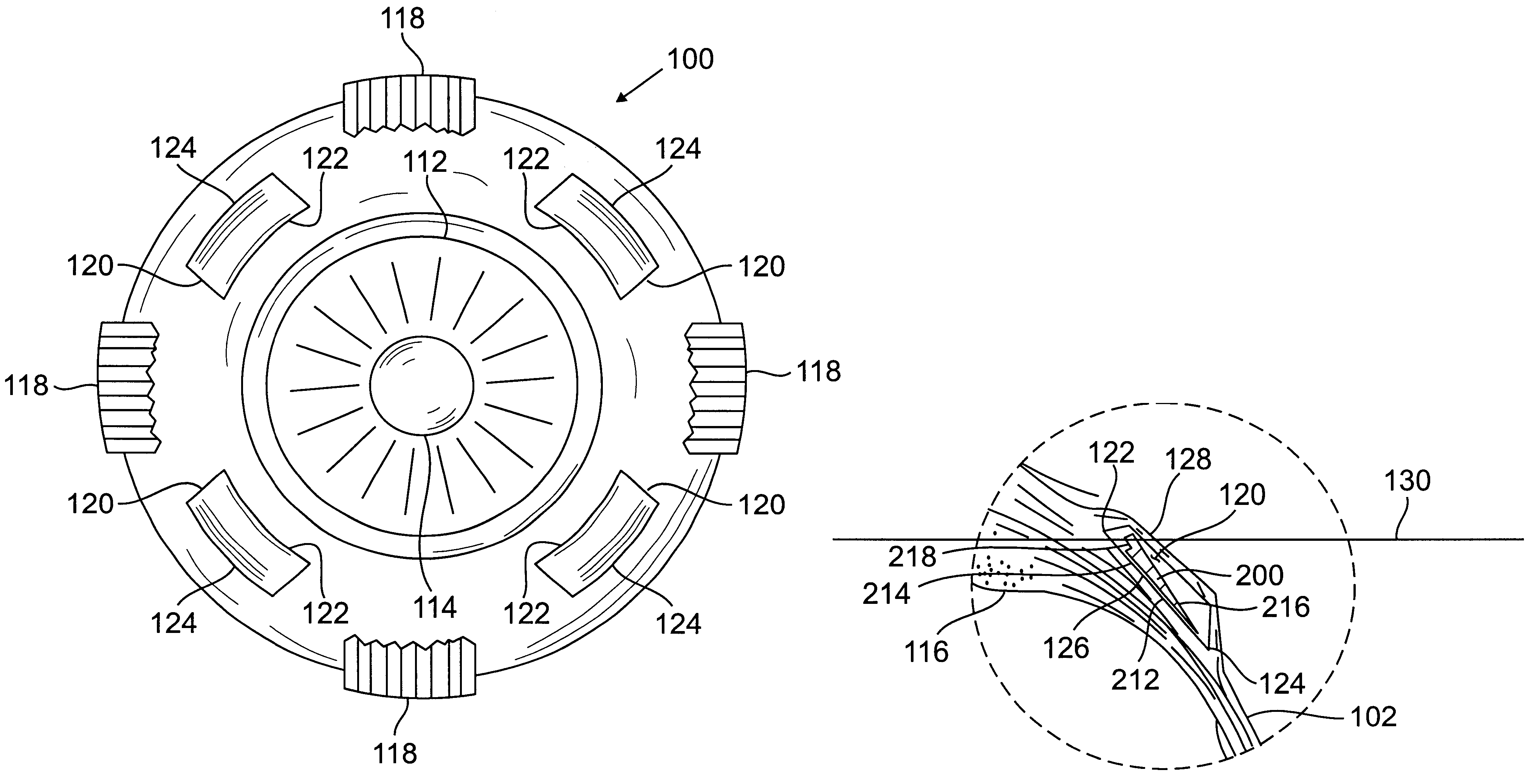
the prosthesis of the invention is illustrated in FIGS. 6-8. FIG. 6 shows a plan view of the inner face of the prosthesis 200 having a base 202 with an anterior edge 204, a posterior edge 206, and lateral ends 208 and 210. The inner face 212 is provided with a ridge 214 extending along the length of the major dimension of the elongated base 202FIG. 7 shows a front elevational view of the prosthesis of FIG. 6 showing the flat, smooth outer surface 216 of the prosthesis. FIG. 8 shows a side view of the prosthesis showing the outer surface 216, the ridge 214 and a notch 218 on the inner surface 212 of the prosthesis.

FIGS. 9-10 illustrate a prosthesis of the invention having a curved planform adapted to be implanted in a scleral pocket that is curved to match the curvature of the eyeball. The prosthesis 300 of FIGS. 9-10 has a generally planar base 302, curved in the plane of the base 302, having an anterior edge 304, a posterior edge 306, and lateral ends 308 and 310. The inner face 31...


PUM


Abstract

Presbyopia is treated by implanting within a plurality of elongated pockets formed in the tissue of the sclera of the eye transverse to a meridian of the eye, a prosthesis having an elongated body having a first surface and a second surface opposite the first surface to contact the base and flap of the scleral pocket. The first and second surfaces are spaced apart a distance so that the implanted prosthesis exerts an outward force on the flap of the scleral pocket which results in an outward traction on at least the anterior margin of the scleral pocket. The combined effect of the implanted prostheses is to exert a radially outward traction on the sclera in the region overlying the ciliary body which expands the sclera in the affected region together with the underlying ciliary body. The expansion of the ciliary body restores the effective working distance of the ciliary muscle in the presbyopic eye and thereby increases the amplitude of accommodation. Hyperopia, primary open angle glaucoma and / or ocular hypertension can be treated by increasing the effective working distance of the ciliary muscle according to the invention. A preferred embodiment of the scleral prosthesis has a major surface adapted to contact the base or flap of the pocket and an opposite surface or ridge spaced from the major surface.

Description

1. Field of the InventionThis invention relates to methods of treating presbyopia, hyperopia, primary open angle glaucoma and ocular hypertension and more particularly to methods of treating these diseases by increasing the effective working distance of the ciliary muscle. The invention also relates to increasing the amplitude of accommodation of the eye by increasing the effective working range of the ciliary muscle.2. Brief Description of the Prior ArtIn order for the human eye to have clear vision of objects at different distances, the effective focal length of the eye must be adjusted to keep the image of the object focused as sharply as possible on the retina. This change in effective focal length is known as accommodation and is accomplished in the eye by varying the shape of the crystalline lens. Generally, in the unaccommodated emmetropic eye the curvature of the lens is such that distant objects are sharply imaged on the retina. In the unaccommodated eye near objects are no...

Claims


Application Information

Patent Timeline
Patent Type & Authority Patents(United States)
IPC IPC(8): A61F2/14A61F9/00A61F9/007
CPCA61F2/147A61F9/00781A61F9/0017Y10S623/905A61F9/0081
Inventor SCHACHAR, RONALD A.
Owner REFOCUS GROUP
Why Eureka
Try Eureka