
Method of determining system volume of a dialysis machine

a dialysis machine and system volume technology, applied in the field of machines, can solve the problems of increasing system volume, difficult and expensive control of dialysate concentrate quantity and formulation in individual vessels, and conductivity measurements that are out of the desired rang

Inactive Publication Date: 2001-08-28
HHD LLC A DELAWARE LLC +2
View PDF14 Cites 75 Cited by
  • Summary
  • Abstract
  • Description
  • Claims
  • Application Information

AI Technical Summary

Problems solved by technology

First, precise control of the quantity and formulation of the dialysate concentrates in their individual vessels is difficult and expensive.
If the tank and associated dialysate fluid circuit are subject to heat disinfection cycles, this can cause a slight expansion of the components resulting in an increase in system volume.
It has been determined that even small fluctuations in total system volume can cause conductivity measurements that are out of a desired range, unless the quantity of the bicarbonate and liquid acid concentrates added during the preparation of the batch of dialysate are precisely controlled.
The present inventors have further appreciated that the process of preparing a batch of dialysate solution has its own difficulties, including the instability of the solution during the process of mixing the solution, the possibility of loss of carbon dioxide gas from the bicarbonate solution and resulting precipitation of calcium carbonate in the dialysate tank, and a substantial amount time being required to thoroughly mix a batch quantity of solution automatically in a compact machine suitable for use in environments outside of traditional dialysis clinic settings.
If you were to add the liquid acid when the bicarbonate is not fully dissolved or is highly concentrated, the resulting solution is unstable and loss of carbon dioxide gas from the tank can produce calcium precipitation at the bottom of the tank.
Further, the above procedure can shorten the total amount of time required to prepare the physiologic solution.

Method used


Image

  • Method of determining system volume of a dialysis machine
  • Method of determining system volume of a dialysis machine
  • Method of determining system volume of a dialysis machine

Examples


Embodiment Construction

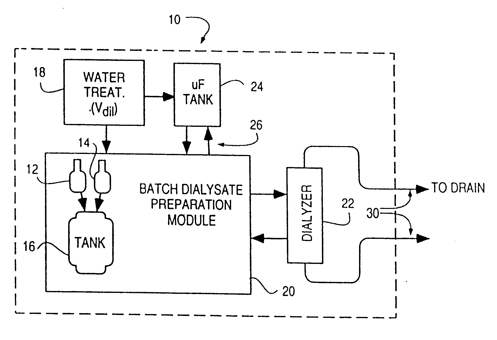
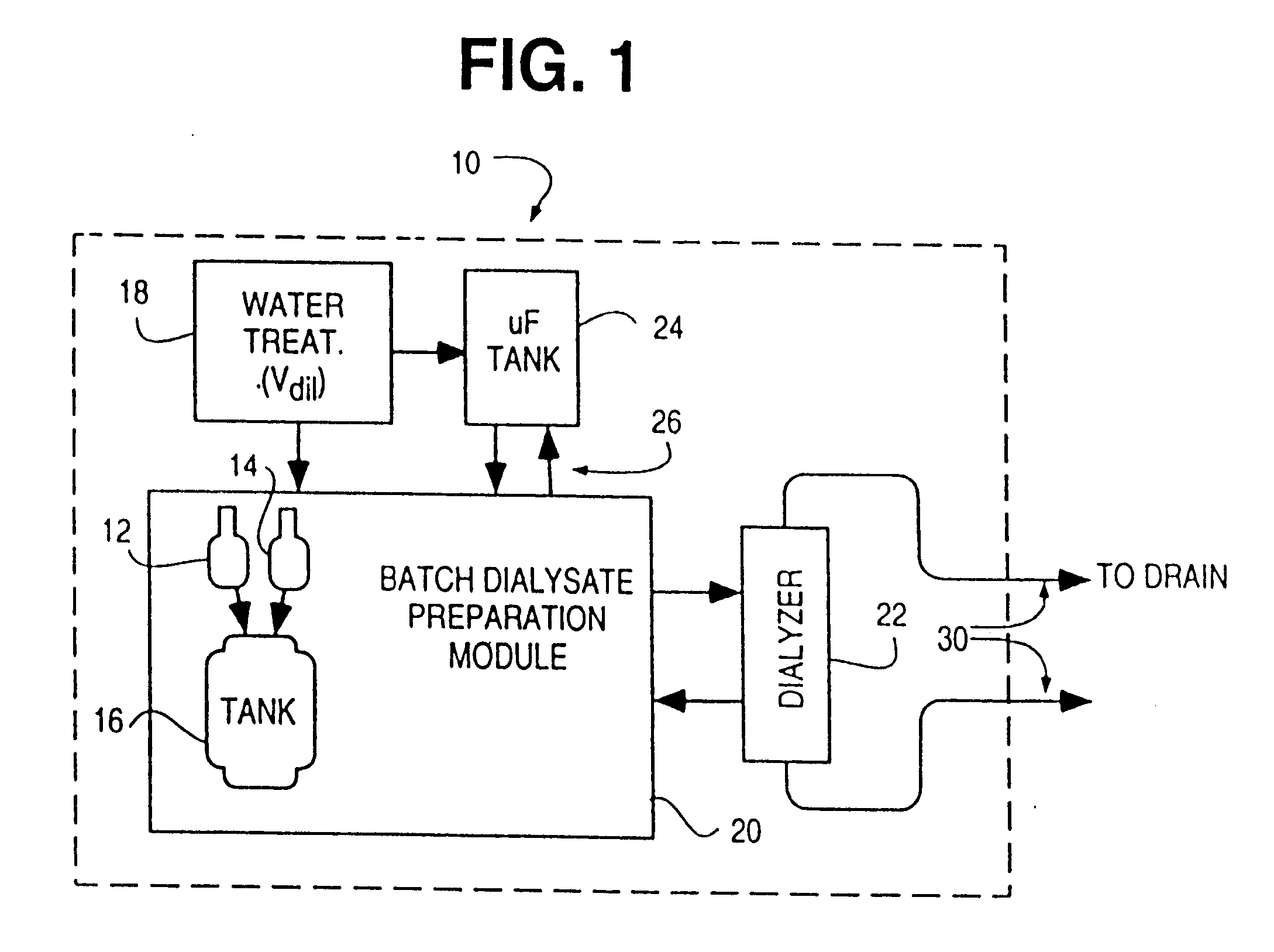
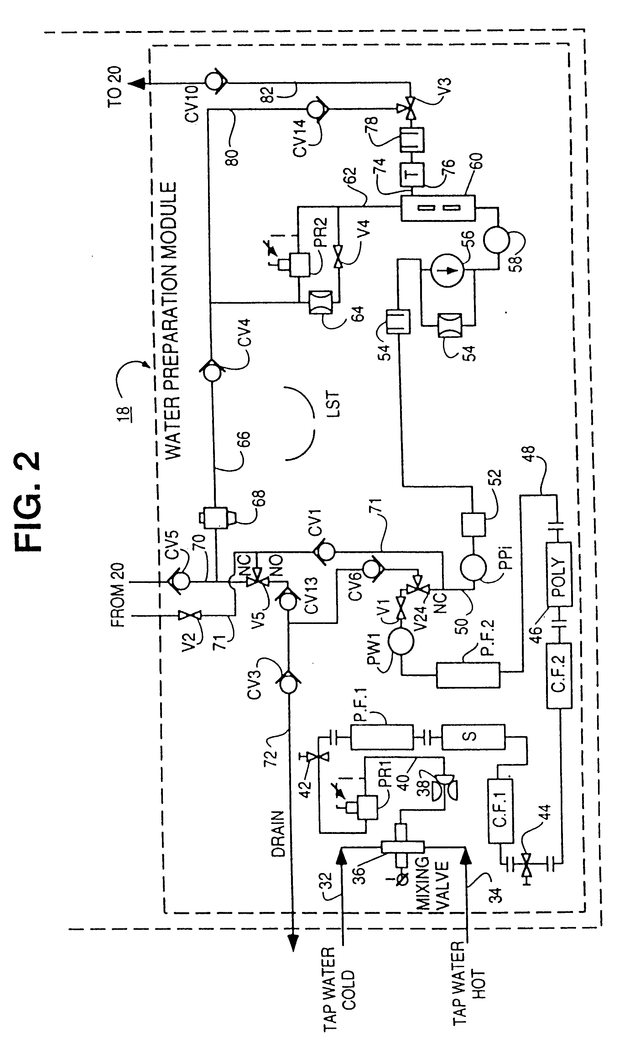
Referring to FIG. 1, the preferred embodiment of the present invention is used in conjunction with a dialysis machine 10 that prepares a batch of dialysate. To prepare the batch of dialysate, two batch quantity chemical vessels 12, 14 are provided that store a concentrated bicarbonate powder formulation and a liquid acid concentrate, respectively. In one embodiment, at the time of preparation of the dialysate, the vessels 12, 14 are opened and their contents dispersed into a dialysate preparation tank 16. The tank 16 is then filled with reverse-osmosis filtered water from a water preparation and treatment module 18 or equivalent supply means. The resulting solution is mixed by circulation in a closed loop in a batch dialysate preparation module 20, for example by swirling action in the tank 16, withdrawal of the solution from the bottom of the tank 16 and reintroduction of the solution into the top of the tank 16.

The total volume of the dialysate fluid circuit path in module 20 incl...


PUM

PropertyMeasurementUnit
conductivityaaaaaaaaaa
volumeaaaaaaaaaa
volumeaaaaaaaaaa

Abstract

A method of calibrating a dialysis machine to determine the volume of a dialysate flow path of the machine including a dialysate preparation tank includes the steps of introducing a known quantity of electrically conductive chemicals into the dialysate preparation tank, filling the dialysate solution flow path with water, mixing the chemicals with water to form a solution, measuring the conductivity of the solution, calculating the system volume (Vsys) according to the relation: Vsys=M / (a1r+b1) where M is the mass in grams of the chemicals, a1 and b1 are a coefficient of linearity and a constant of linearity, respectively, for the chemicals and r is the measured conductivity of the solution.

Description

A. Field of the InventionThis invention relates generally to machines that are used to prepare a physiological solution from a batch of chemicals, such as dialysis machines, including peritoneal and hemodialysis machines. More particularly, the invention relates to the process by which the solution is prepared and the conductivity of the solution is adjusted. The invention is particularly useful in conjunction with a machine that prepares and stores an entire batch of solution, such as a batch dialysate preparation system for a dialysis machine, as opposed to machines based on so-called "proportioning" systems, in which the solution is prepared continuously during the treatment session.B. Statement of Related ArtDialysis, including hemodialysis and peritoneal dialysis, is a treatment for patients that suffer from inadequate kidney function. In hemodialysis, blood is pumped from the patient's body through an extracorporeal artificial kidney circuit to a dialyzer. Blood-borne toxins a...

Claims


Application Information

Patent Timeline
Patent Type & Authority Patents(United States)
IPC IPC(8): A61M1/16A61M1/14A61L2/04A61L2/18A61M1/34A61M1/36A61M39/16B01D17/00B01D17/09B01D61/02B01D61/04B01D61/12B01D61/24B01D65/02B01D65/10C02F1/28C02F1/44C02F1/68F16K17/04
CPCA61L2/04A61M1/365A61M1/16A61M1/1656A61M1/1686A61M1/169A61M1/1692A61M1/1694A61M1/3626A61M1/3627A61M1/3639A61M1/3643B01D61/02B01D61/025B01D61/04B01D61/12B01D65/022B01D65/102C02F1/441F16K17/0453A61L2/18A61M1/3649A61M1/1607A61M1/1609A61M1/1649A61M1/165A61M1/166A61M1/1662A61M1/1666A61M1/1668A61M1/1672A61M1/1682A61M1/1684A61M1/1688A61M1/3431A61M1/3434A61M1/3437A61M1/3465A61M1/3629A61M1/3641A61M1/3646A61M1/3647A61M1/1658A61M39/16A61M2205/12A61M2205/15A61M2205/17A61M2205/3382A61M2205/3386A61M2205/505A61M2205/6072A61M2205/705A61M2205/707A61M2205/7554A61M2205/7581A61M2206/11B01D2311/04B01D2321/08B01D2311/10A61M1/3462A61M1/28A61M2205/3317A61M2205/3324A61M1/1601A61M1/3644
Inventor SHAH, DILIP H.WIEBENSON, DEREKBROSE, TOM L.MALIEKKAL, SHINCY
Owner HHD LLC A DELAWARE LLC
Learn More