Torque converter blades brazed to a housing using a magnetic heating process

a technology of torque converter blades and magnetic heating processes, which is applied in the direction of forging/pressing/hammering equipment, soldering equipment, forging/pressing/hammering equipment, etc., and can solve the problems of insufficient structural deflection of the housing in service, time-consuming, and insufficient brazing

Inactive Publication Date: 2001-09-04
FORD GLOBAL TECH LLC
View PDF17 Cites 11 Cited by
  • Summary
  • Abstract
  • Description
  • Claims
  • Application Information

AI Technical Summary

Problems solved by technology

The process described in the '365 patent is very effective but time consuming as the laser beam must traverse each of the blades in order to secure each blade to the housing.
As further described in the '365 patent, a

Method used


Image

  • Torque converter blades brazed to a housing using a magnetic heating process
  • Torque converter blades brazed to a housing using a magnetic heating process
  • Torque converter blades brazed to a housing using a magnetic heating process

Examples


Embodiment Construction

)

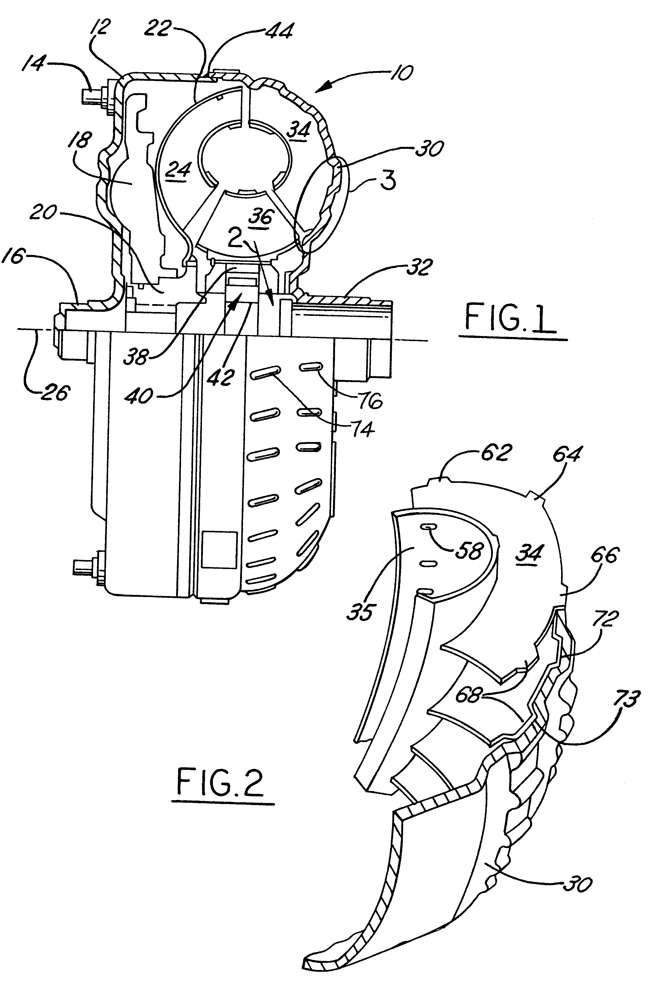
Referring to FIG. 1, an automotive torque converter or fluid coupling 10 for an automatic transmission includes a cover 12 adapted for connection by a mechanical attachment to a flywheel (not shown) which is adapted to be driven by an engine crankshaft. The cover 12 is supported on a surface 16 which is adapted to fit within a recess formed on the end of the engine crank shaft. A lockup clutch 18 is rotatably supported on the hub 20 of a turbine rotor 22, which includes multiple turbine blades 24, rotatably supported on the hub 20 and distributed angularly about a longitudinal axis 26 extending along the length of the torque converter parallel to the engine crank shaft. Following assembly, the torque converter is substantially symmetric about the axis 26.

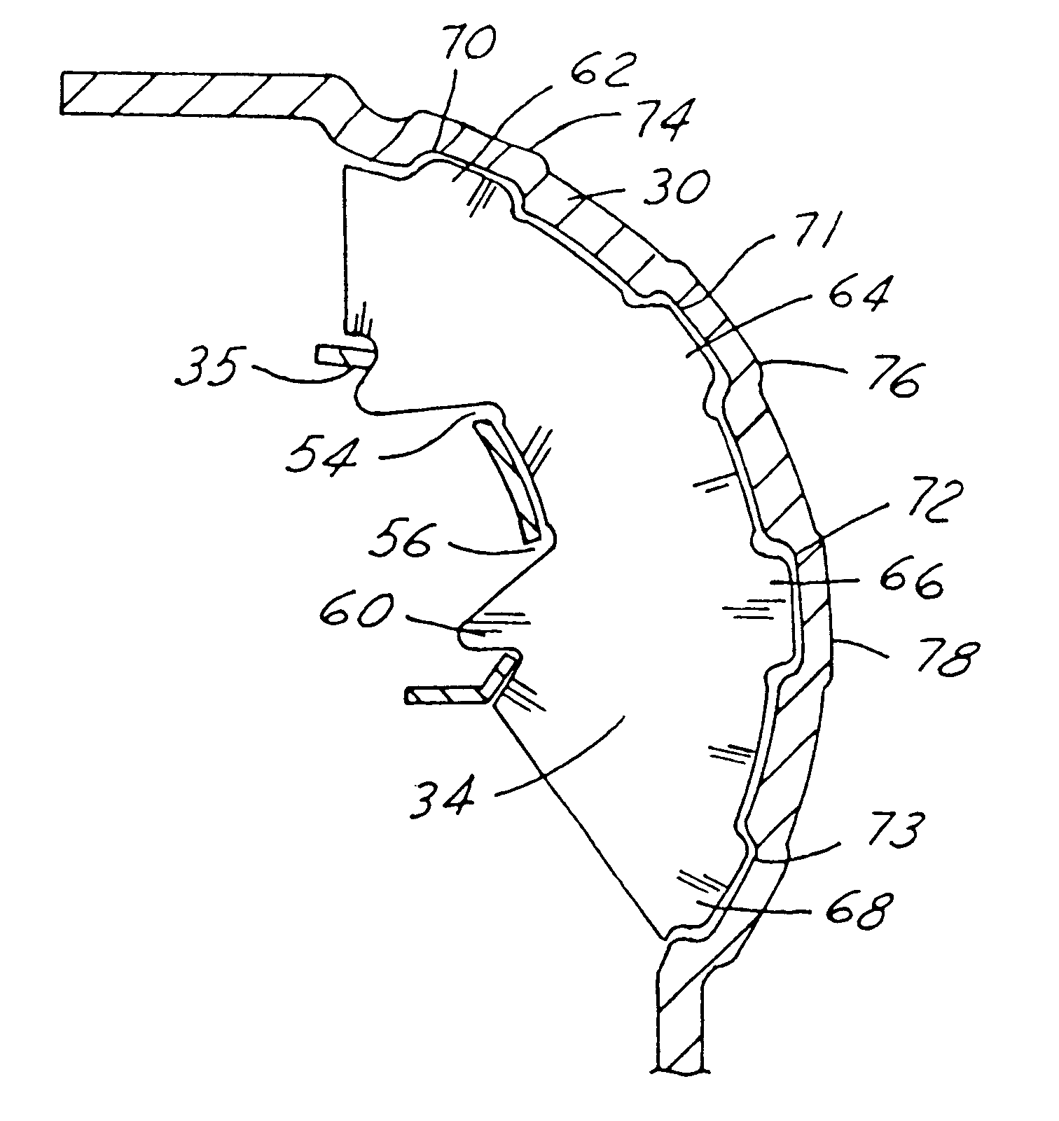
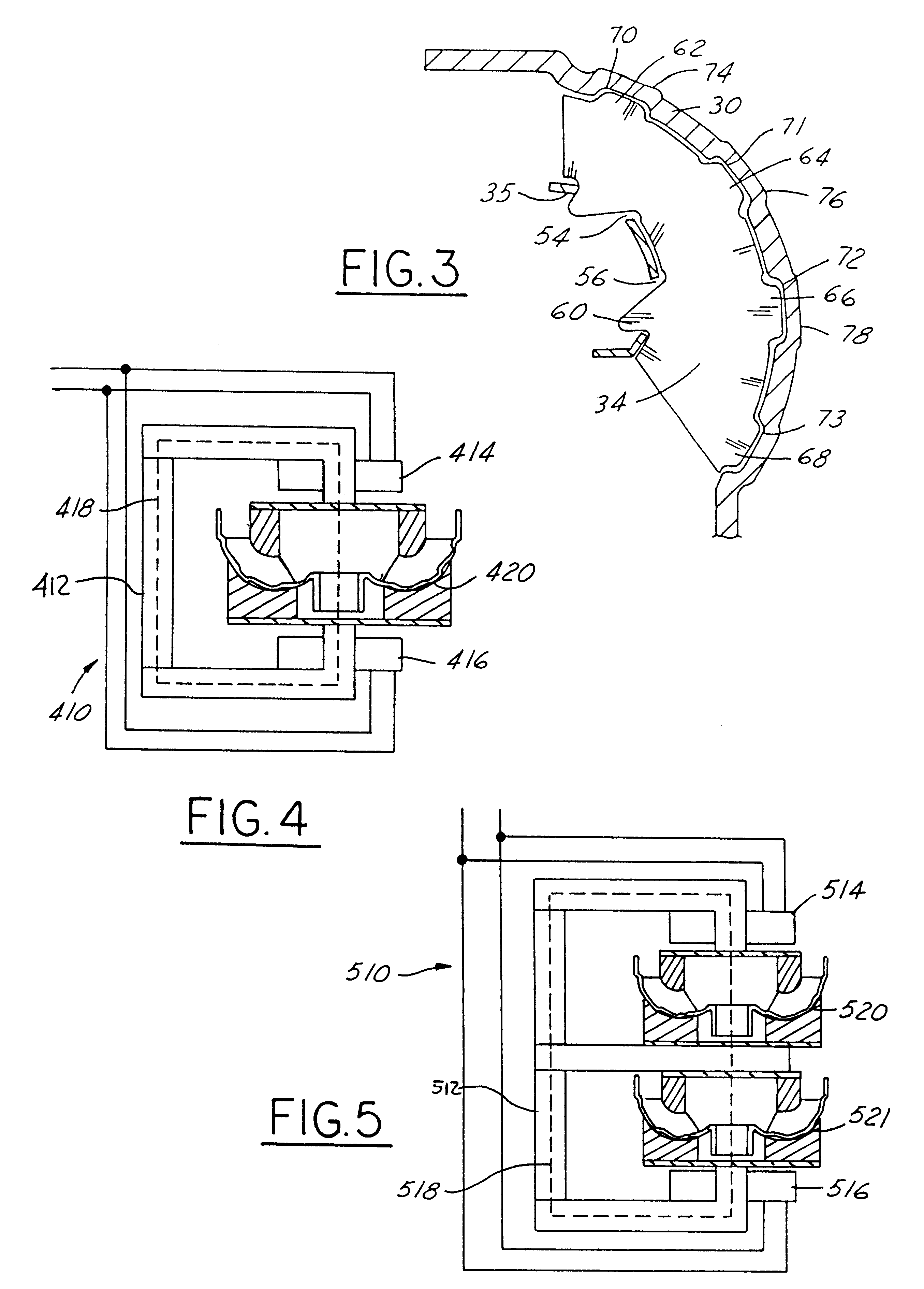
An impeller housing 30 is rotatably supported on the impeller hub 32 and contains multiple impeller blades 34, spaced from one another angularly about the axis 26. Alternatively, the impeller may be referred to as a pump. The impel...


PUM

PropertyMeasurementUnit
Lengthaaaaaaaaaa

Abstract

A method for making a torque converter includes the steps of forming a blade having a tab extending outward from the blade and along a portion of a length of the blade. A recess is formed in the housing sized to receive the first tab. The recess defines an edge adjacent the tab and extending along the tab. The tab is inserted within the recess to form a housing assembly. A brazing material is provided between the tab and the housing. The assembly is positioned within a magnetic heating machine and magnetically heated

Description

The present invention relates to a torque converter impeller or turbine and brazing process therefor using a magnetic field heating. More particularly, it pertains to brazing thin sheet metal blades of a fluid coupling or torque converter to a housing.DESCRIPTION OF THE PRIOR ARTOur invention relates generally to a hydrokinetic torque transmitting mechanism, and more particularly to an improvement in the construction and assembly of components of a bladed hydrokinetic member such as the impeller of a torque converter or fluid coupling.U.S. Pat. No. 4,868,365, assigned to the assignee of the present invention, which is incorporated herein by reference in its entirety, describes a method for using a laser welding beam to weld the blades to a torque converter housing. The process described in the '365 patent is very effective but time consuming as the laser beam must traverse each of the blades in order to secure each blade to the housing. As further described in the '365 patent, at co...

Claims


Application Information

Patent Timeline
IPC IPC(8): B23K1/00B23P15/00F16H41/00F16H41/28
CPCB23K1/00B23P15/006F16H41/28Y10T29/49316Y10T29/4933
Inventor KOLODZIEJ, DENNIS RAYMONDWILSON, JILL MARIE
Owner FORD GLOBAL TECH LLC
Why Eureka
Try Eureka